Two Colour LED Module with Arduino
Gradually alternate between colours with the two colour led module and the Arduino!
Written By: Cherie Tan
Difficulty
Easy
Steps
7
Gradually alternate between two colours with this LED module! In this guide, learn to create a fading effect with this two colour LED module and the Arduino. After completing this guide, you will understand how to fade an LED using a simple program with the Arduino IDE.
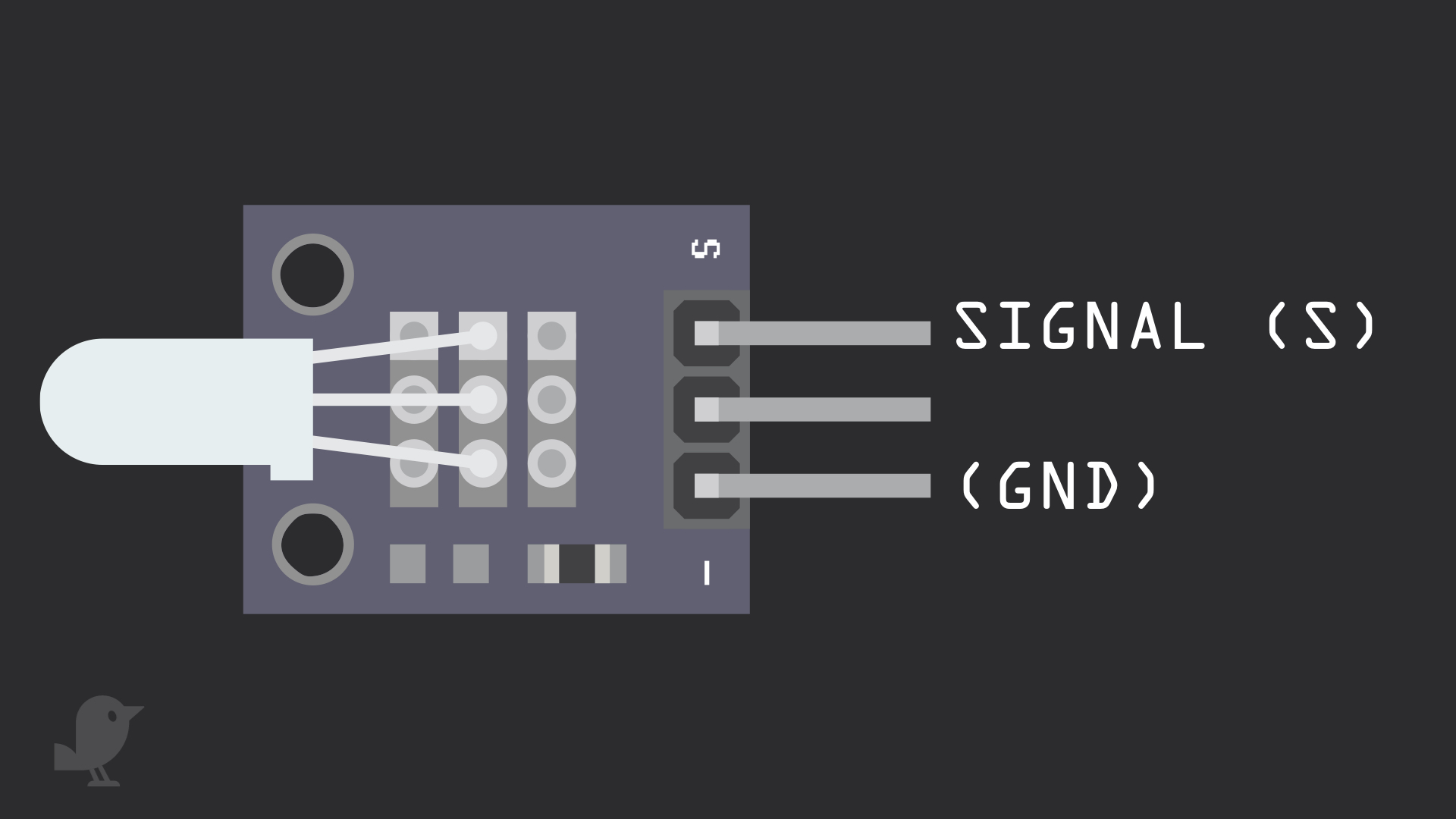
Let's take a closer look at the Two Colour LED module! This is a KY-011 LED module which provides a red and green LED connected with a common cathode. Since the operating voltage is 2.0V-2.5V, you'll need a current limiting resistor to avoid burnout when connected up to the Arduino. There are three pins starting with the one on the furthest left. Signal: This pin is a signal pin, and can be used to emit a green light. Middle Pin : This pin is another signal pin, and can be used to emit a red light. GND: Though it is labelled '-' on the module, this is the ground pin also known as 'GND'. What is 'GND'? In electronics, we define a point in a circuit to be a kind of zero volts or 0V reference point, on which to base all other voltage measurements. This point is called ground or GND.

Insert the LED module into the breadboard as shown.

Next, insert the resistors so that one end of each are connected to the S pin and middle pin respectively.

Connect a jumper wire from the S pin to Digital Pin 10. Make sure you're using a resistor as shown.
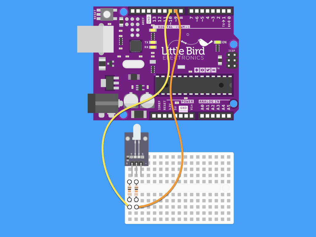
Next, connect a jumper wire from the middle pin to Digital Pin 9. Notice how both Digital Pins used have a ~ symbol next to them? On Arduino Uno, the PWM pins are labelled with a ~ sign. You can see these are Pins 3, 5, 6, 9, 10 and 11.
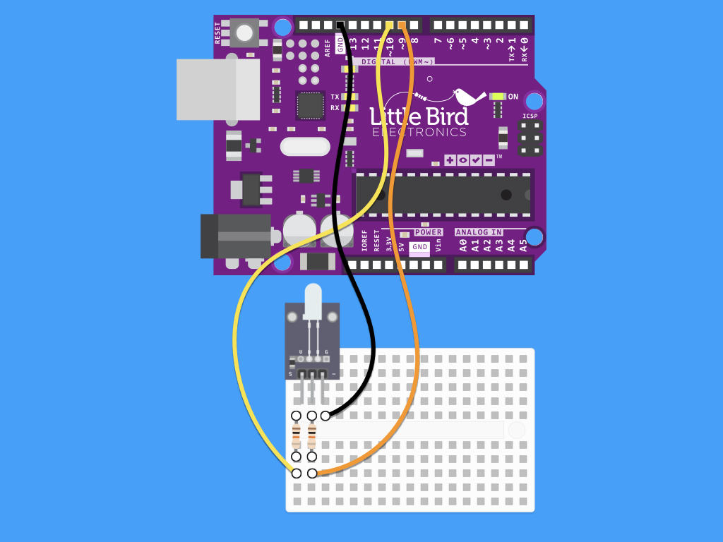
Finally, connect a jumper wire from the - Pin to GND on the Arduino. Any of the GND pins found on the Arduino will work.
int redpin = 9; // pin for red signal
int greenpin = 10; // pin for green signal
int val;

void setup() {
  pinMode(redpin, OUTPUT);
  pinMode(greenpin, OUTPUT);
}

void loop() {
  for(val = 255; val > 0; val--) {
    analogWrite(redpin, val); //dim red
    analogWrite(greenpin, 255 - val); // brighten green
    delay(15);
  }
  for(val = 0; val < 255; val++) {
    analogWrite(redpin, val); //brighten red
    analogWrite(greenpin, 255 - val); //dim green
    delay(15);
  }
}
You can adjust the amount of each colour using pulse-width modulation (PWM). Within the Arduino IDE is a built-in function called analogWrite(). This function can be used to generate a PWM signal. Using this function, we can give a value of 0-255. analogWrite(0) means a signal of 0% duty cycle. analogWrite(127) means a signal of 50% duty cycle. analogWrite(255) means a signal of 100% duty cycle. Now go ahead and copy and paste this code into the Arduino IDE. Make sure the right board and port is selected; These should mention (Arduino Uno). Watch how the LED gradually alternates between green and red!