TrinityPixel LED Strips and Raspberry Pi
Starter guide on using the TrinityPixel LED strips for Raspberry Pi
Written By: Cherie Tan
Difficulty
Medium
Steps
18
Putting together a huge number of LEDs into an electronic project may seem tedious. Here at Little Bird Electronics, we have these TrinityPixel LED RGB strips. These are waterproof and flexible LED strips based on the popular and extremely compact WS2812B LED driver, integrated directly into a 5050 package.
In this guide, learn to connect it to the Raspberry Pi with a logic level converter chip, install the necessary libraries, and get started with programming it!
Complete this guide to start building bright and beautiful indoor or outdoor lighting, festive decorations, light-up gear, or even integrate it into your next home automation project.
Putting together a huge number of LEDs into an electronic project may seem tedious, but not with the TrinityPixel LED RGB strips. These are water-proof, flexible, digitally-addressable LED strips based on the extremely compact WS2812B LED driver, integrated directly into a 5050 package. With it, you can manually set the colour of each LED's red, green, and blue component with 8-bit PWM precision. The strip can also be shortened or lengthened to your liking.
These LED chips are called SMD 5050 due to its dimensions, which are 5.00mm by 5.00mm.
Rather than controlling individual LEDs, control the entire strip with just a single digital output pin from a Raspberry Pi. In this guide, we'll show you how to get started with the TrinityPixel LED strips to add lighting effects to your Raspberry Pi project!
Looking for more information? View the datasheet here.
It is possible to connect the 5V pin on the TrinityPixel LED strip to 5V on the Raspberry Pi, but only if you are powering a few LEDs.
Another way to go about it is to use a 1N4001 diode. This method requires the use of a diode that can handle all the current drawn by the TrinityPixels. For example, a diode that can handle 1A average of continuous current, can be used to power only about 16 TrinityPixels at full brightness (white) or about 50 TrinityPixels in various colours (non white).
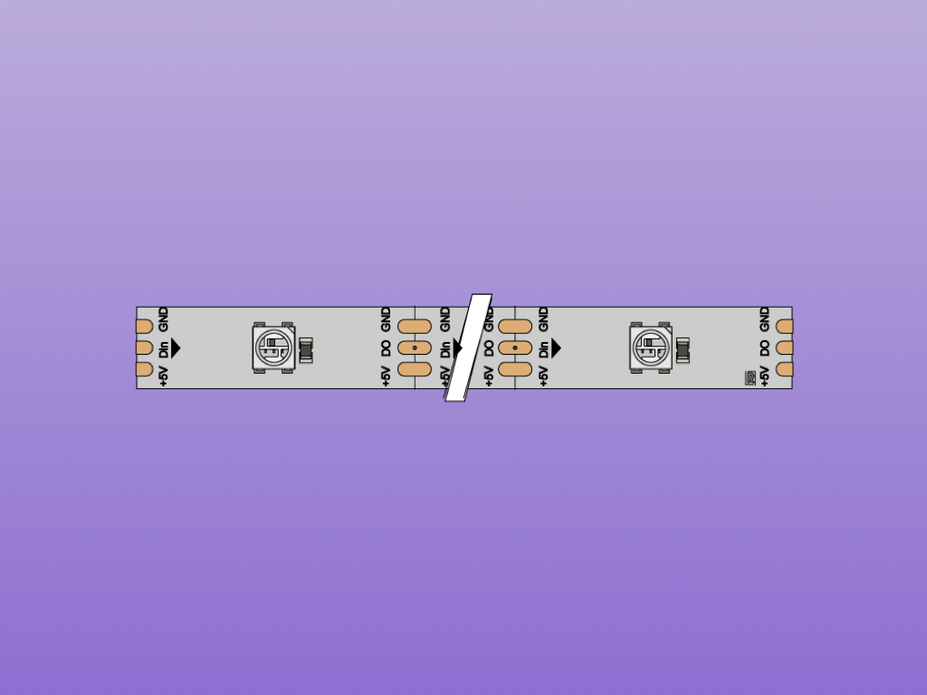
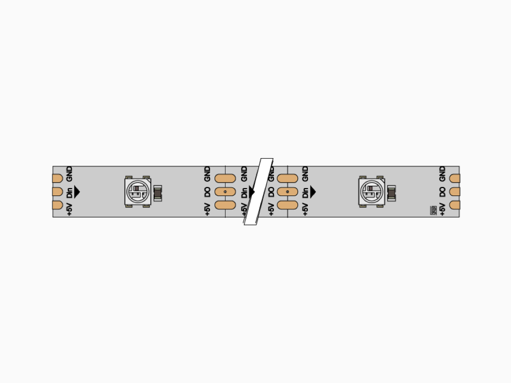
Let's take a closer look at how these LED strips work. On each LED, there are three connectors: +5V, GND, and DIN. Connecting it to the Raspberry Pi is simple, apart from the fact that we need to convert the Raspberry Pi's GPIO pin from 3.3V up to about 5V.
The Raspberry Pi GPIO pins work with 3.3V logic levels and are not 5V tolerant. If you do apply 5V to the GPIO pin, you run the risk of permanently damaging it.
While there are a few methods to convert it from 3.3V to 5V, we'll use a logic level converter chip, the 74AHCT125. By using this method, full brightness that is only limited by the power supply can be achieved.
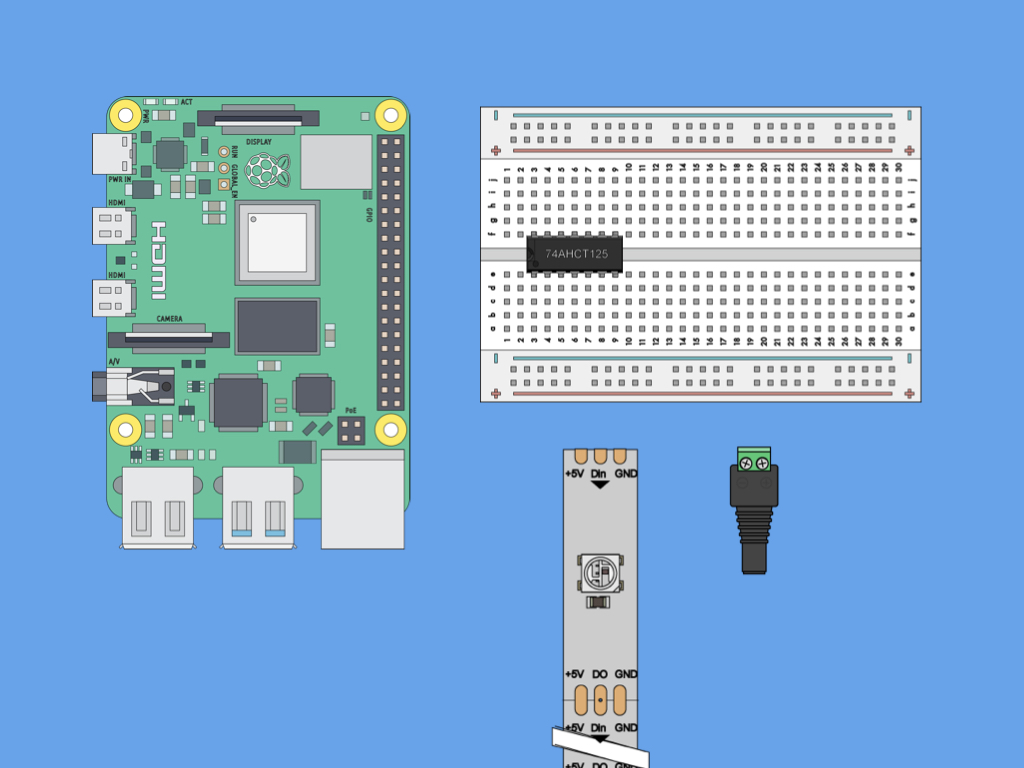
First, place the 74AHCT125 logic level shifting chip into the breadboard as shown. One end should be connected along E3 to E9, while the other side should be connected to F3 to F9.
Please make sure the notch on the 74AHCT125 is facing as shown.
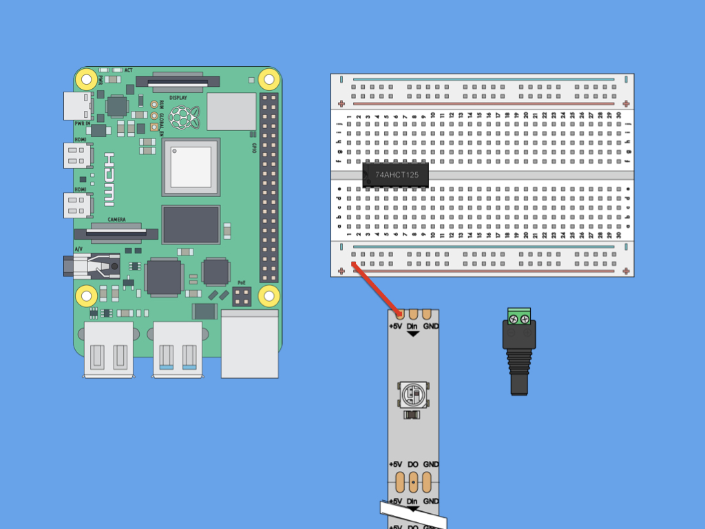
Next, connect the red jumper wire from +5V to the "+" power rail on the breadboard.
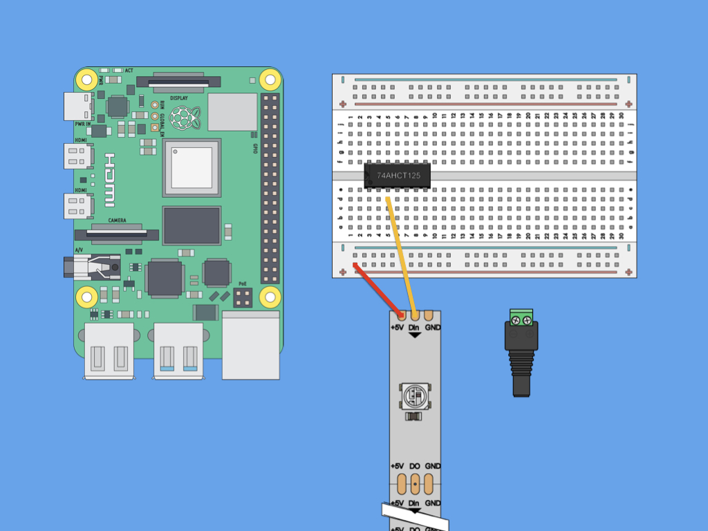
Then connect DIN from the TrinityPixels LED strip to Pin 3 of the 74AHCT125 logic level shifter.
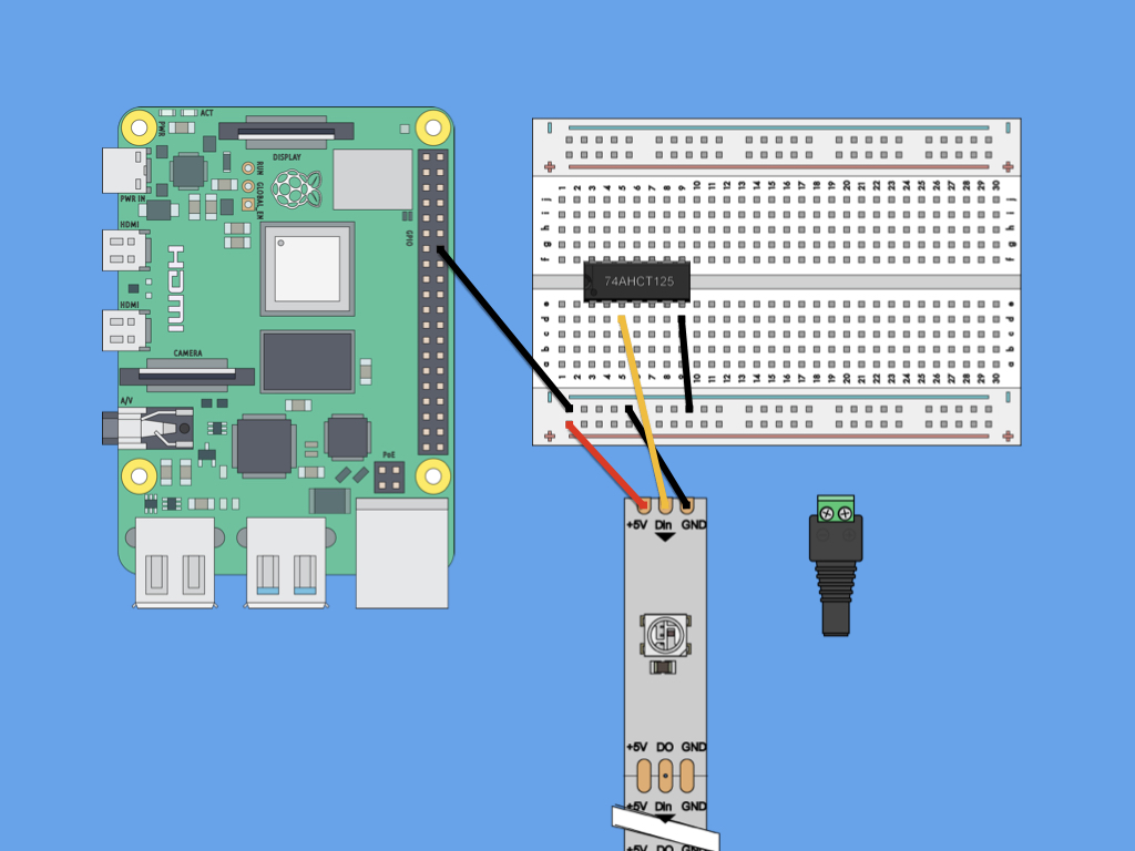
Connect GND from the TrinityPixels LED strip to "-" rail of the breadboard.
Next connect a black jumper wire from "-" rail to Pin 7 (GND) of the 74AHCT125 logic level shifter.
Finally, connect another black jumper wire from "-" rail to Pin 14 (GND) on the Raspberry Pi.
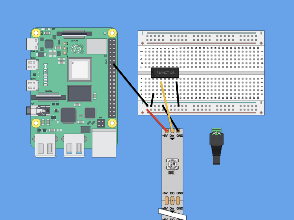
Connect "-" rail to Pin 1 of the 74AHCT125 logic level shifter.
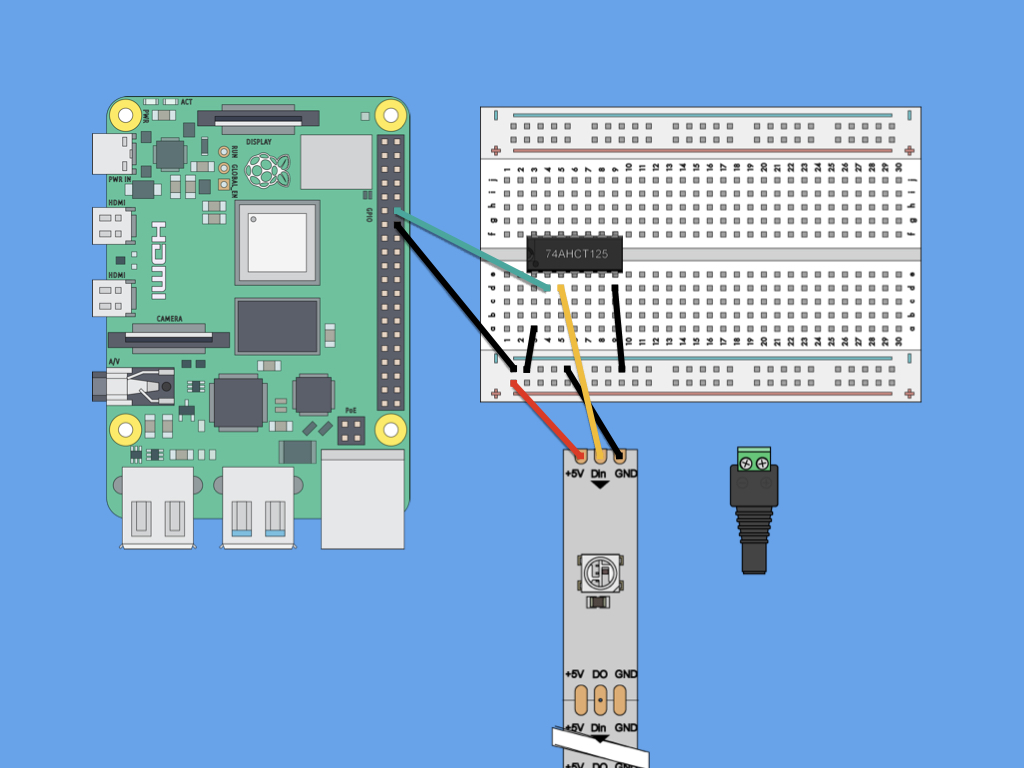
Next, connect a male to female jumper wire from Pin 2 of the 74AHCT125 logic level shifter, to Pin 12 (GPIO18) on the Raspberry Pi.
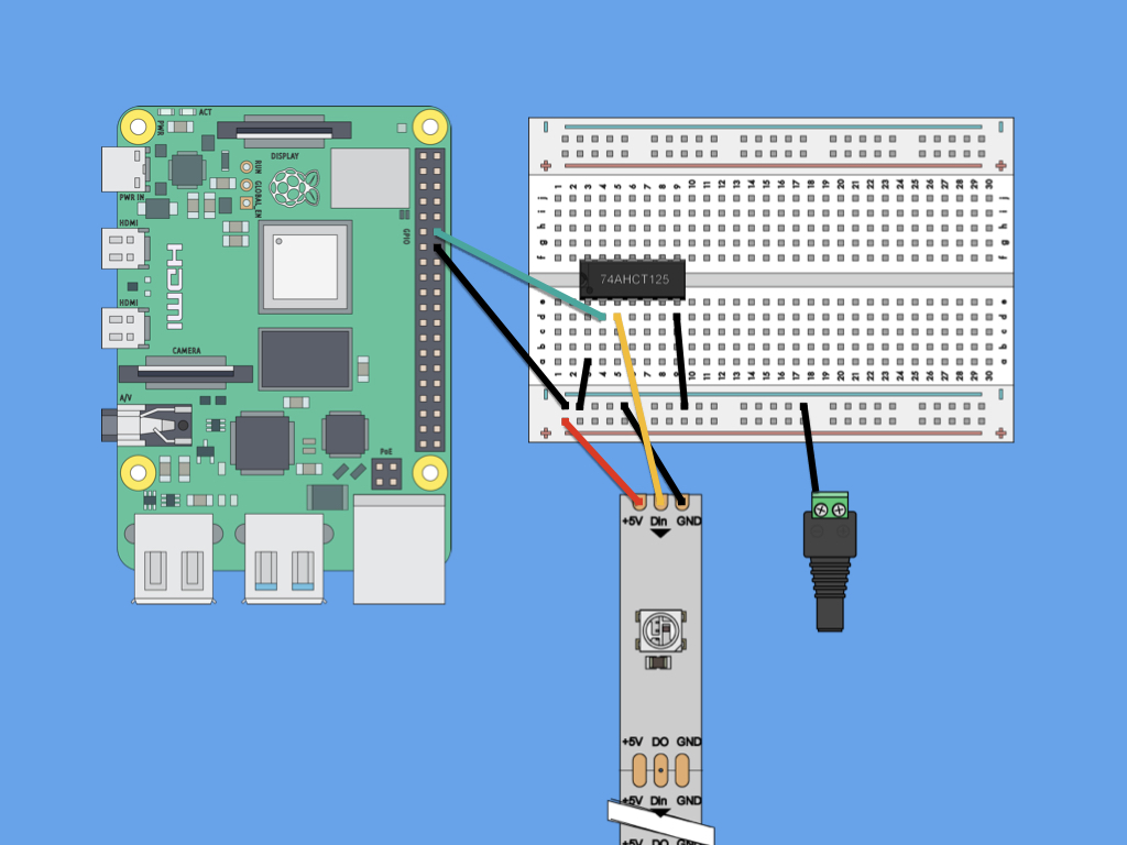
Next, connect a black jumper wire from "-" on the power adapter to "-" rail on the breadboard.
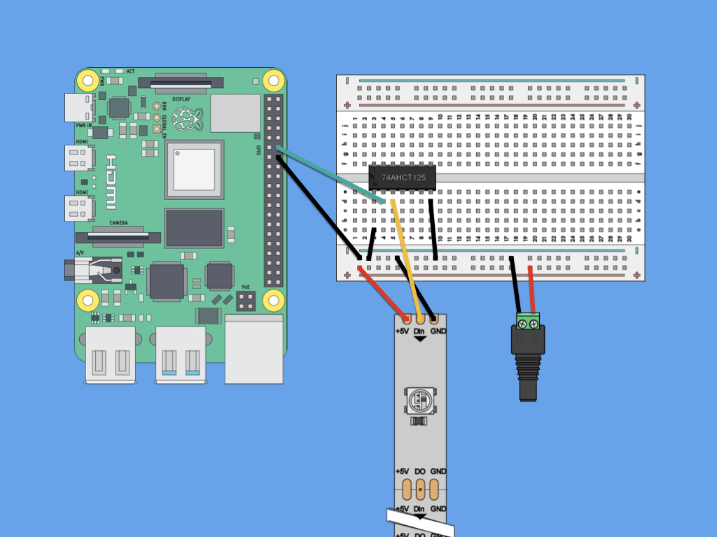
Next, connect "+" on the power adapter to "+" rail on the breadboard.
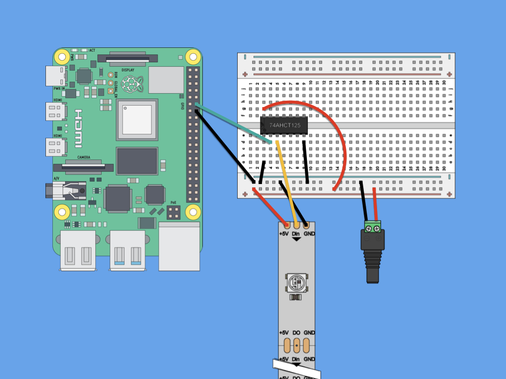
Connect a 5V 2A power supply to the female DC power adapter.
Finally, connect "+" of power rail to Pin 14 of the logic level shifter. This is the VCC pin on the logic level shifter.
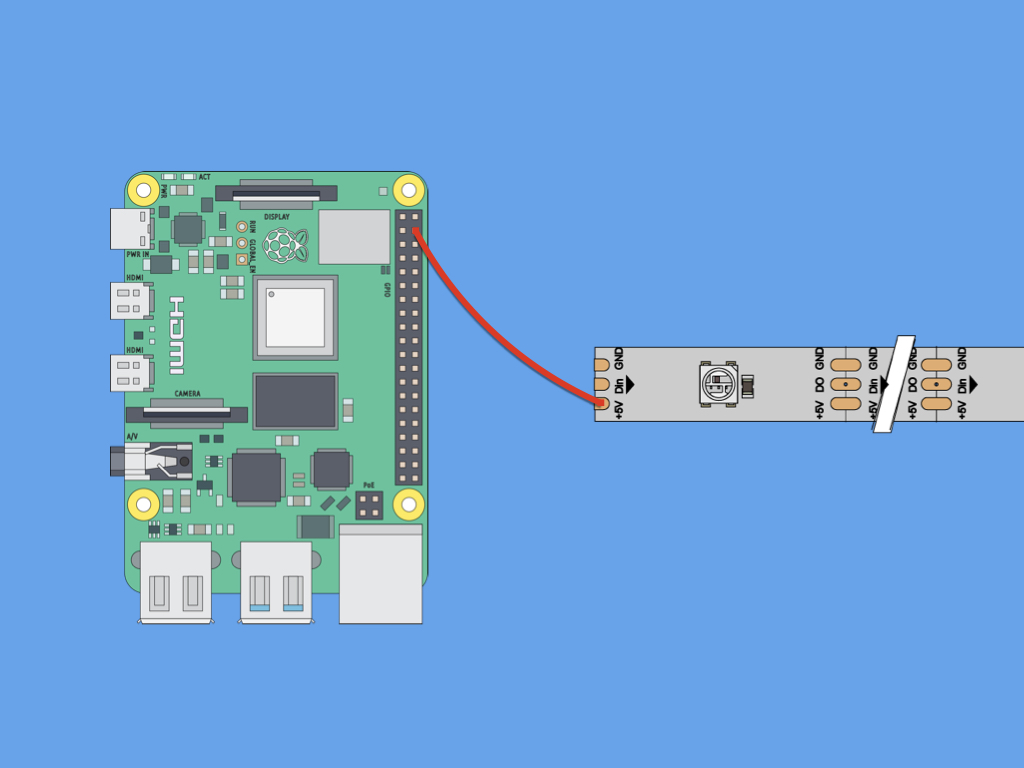
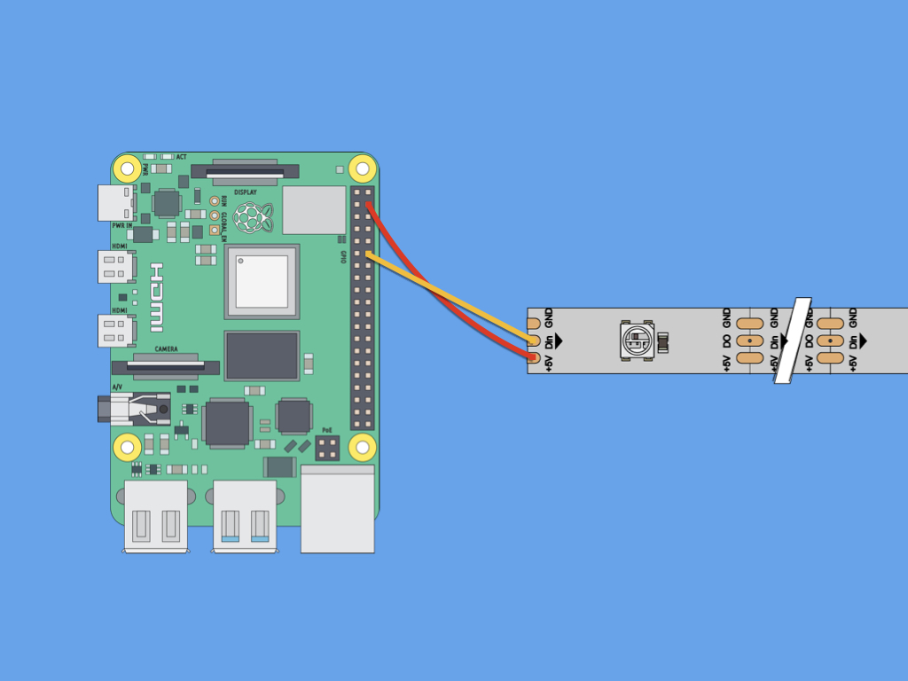
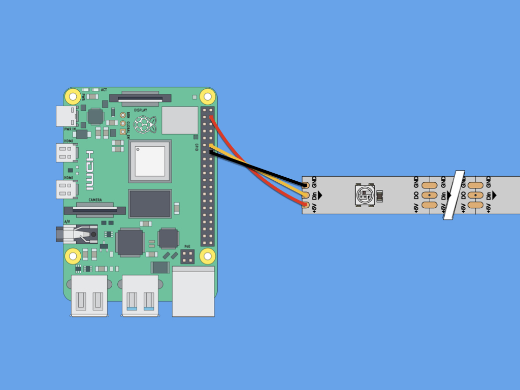
Power up the Raspberry Pi and TrinityPixel LED strips with the USB-C power supply.
If only a few LEDs will be used, you can connect the TrinityPixel LED strip directly to the Raspberry Pi like so:
+5V to 5V
DIN to GPIO18
GND to GND
+5V to 5V
DIN to GPIO18
GND to GND
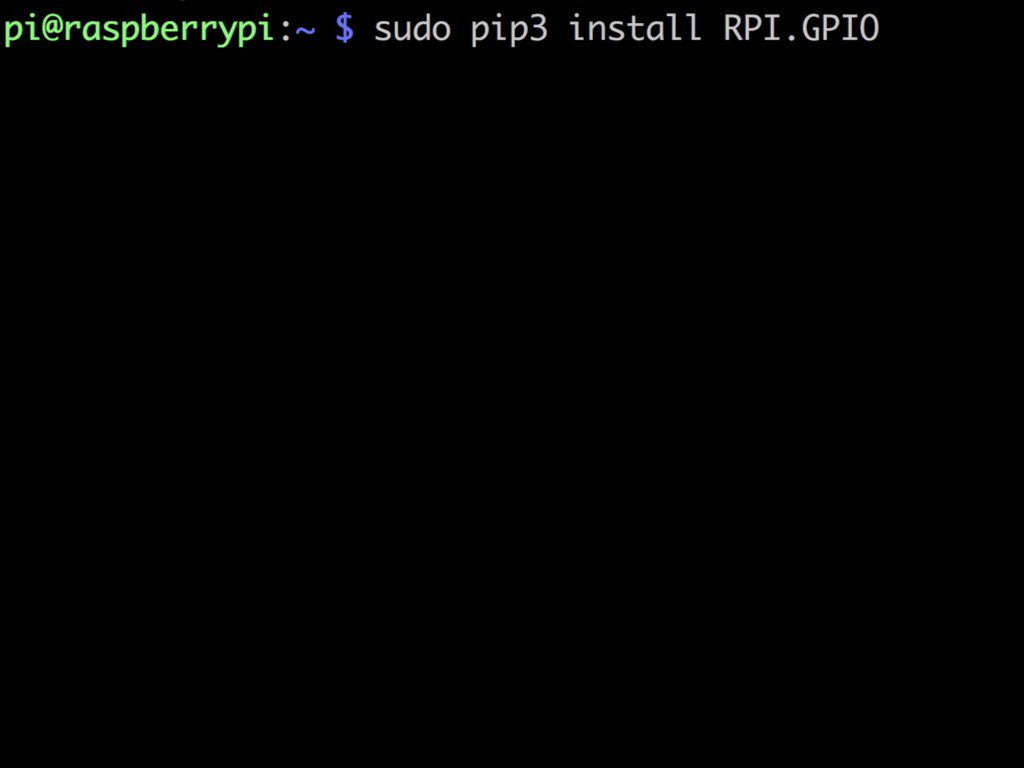
If the RPI.GPIO library has not yet been installed, run this command in the terminal: sudo pip3 install RPI.GPIO
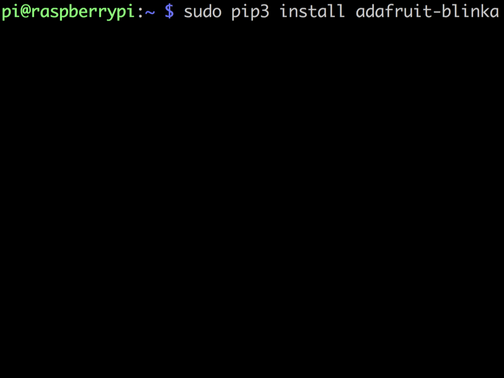
Next, install the adafruit blinka library with the command: sudo pip3 install adafruit-blinka
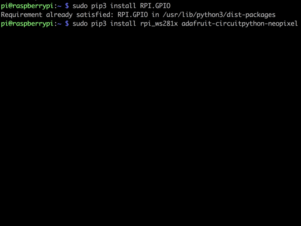
Enter the command: sudo pip3 install rpi_ws281x adafruit-circuitpython-neopixel
import board
import neopixel
pixels = neopixel.NeoPixel(board.D18,4)

pixels[0] = (255,0,0)
Copy and paste the following code into the nano editor.
This first example gets the very first LED to light up in red.
Run the code with: sudo python3 file-name.py
Enter into the terminal: sudo nano file-name.py
Swap file-name with whatever you'd like to call the program.
import board
import neopixel
pixels = neopixel.NeoPixel(board.D18,4)

pixels.fill((0,255,0))
Replace the existing code with the following.
This next example code will get all the LEDs (the first four LEDs) to light up in green. To change the colour, adjust the RGB values in pixels.fill.
Want to change the LED count? Simply change the number in the third parameter of neopixel.NeoPixel.
import board
import neopixel
from time import sleep

LED_COUNT = 8
pixels = neopixel.NeoPixel(board.D18, LED_COUNT)

for x in range(0,LED_COUNT):
    pixels[x] = (255,0,0)
    sleep(1)
Replace the existing code with the following.
The following code uses the sleep function. A for-loop is used to make the first to eight LEDs light up a second apart from each other. The TrinityPixel addressable LEDs start at LED 0.