Sensor Board for micro:bit
Learn to use the sensor board for micro:bit from Monk Makes
Written By: Cherie Tan
Difficulty
Easy
Steps
12
The MonkMakes Sensor Board for micro:bit will easily enable you to sense the sound, temperature and light level around you.
In this guide, learn to connect it to the micro:bit with alligator clips, and program it in the MakeCode Editor and MU Editor.
In this guide, learn to connect it to the micro:bit with alligator clips, and program it in the MakeCode Editor and MU Editor.
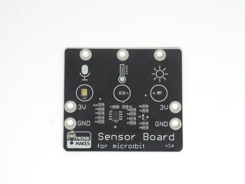
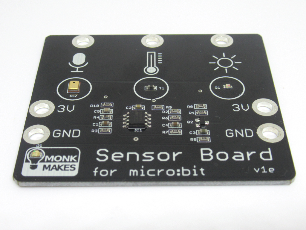
The sensor board for micro:bit from Monk Makes has three built-in sensors that can sense sound, temperature, and light level.
They can be easily connected to the micro:bit with alligator clips, or through the use of the Micro:bit GPIO T-type Expansion Board.
It can be programmed in both the MakeCode editor (Blocks interface and Javascript interface) and in MU editor (Micropython).
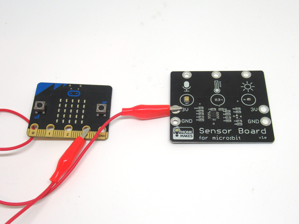
Attach a red alligator clip from 3V on the sensor board to 3.3V on the micro:bit
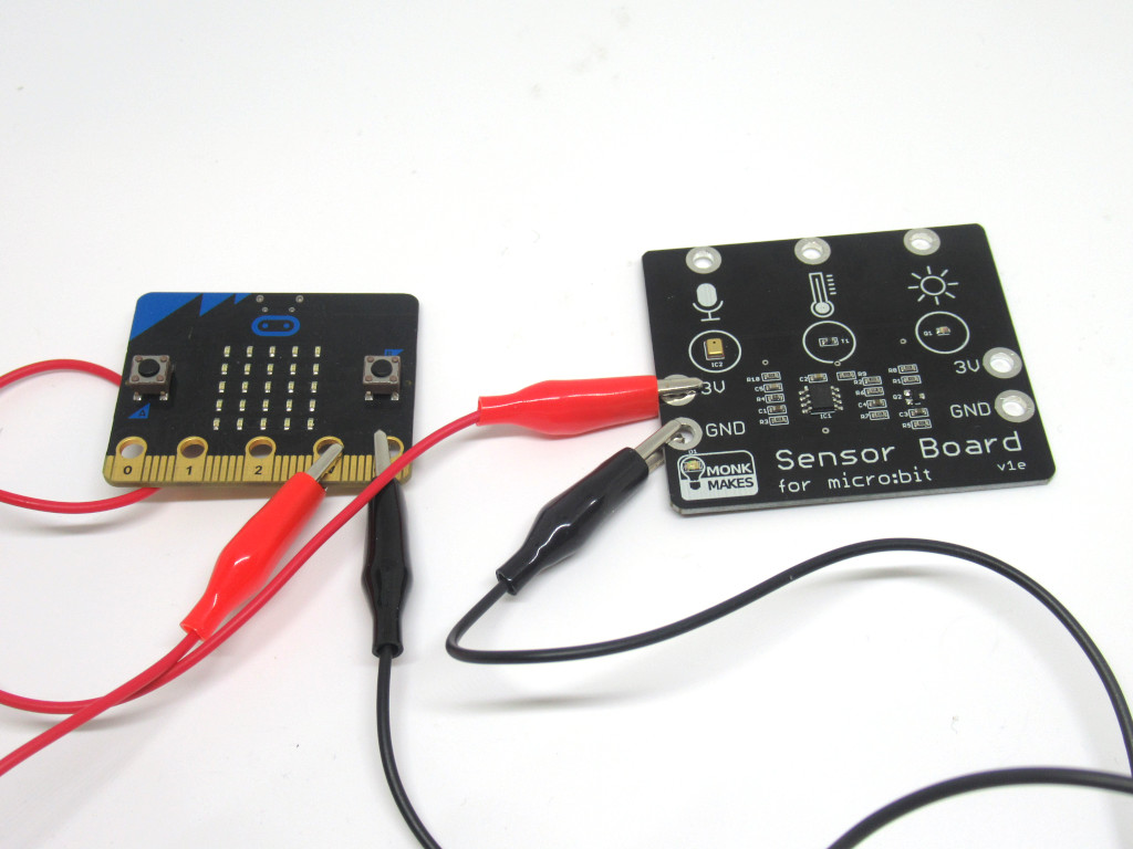
Attach a black alligator clip from GND on the sensor board to GND on the micro:bit
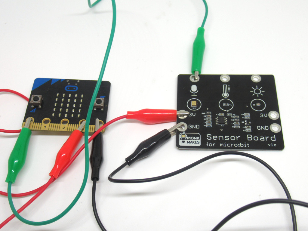
Attach an alligator clip from Sound on the sensor board to P0 on the micro:bit
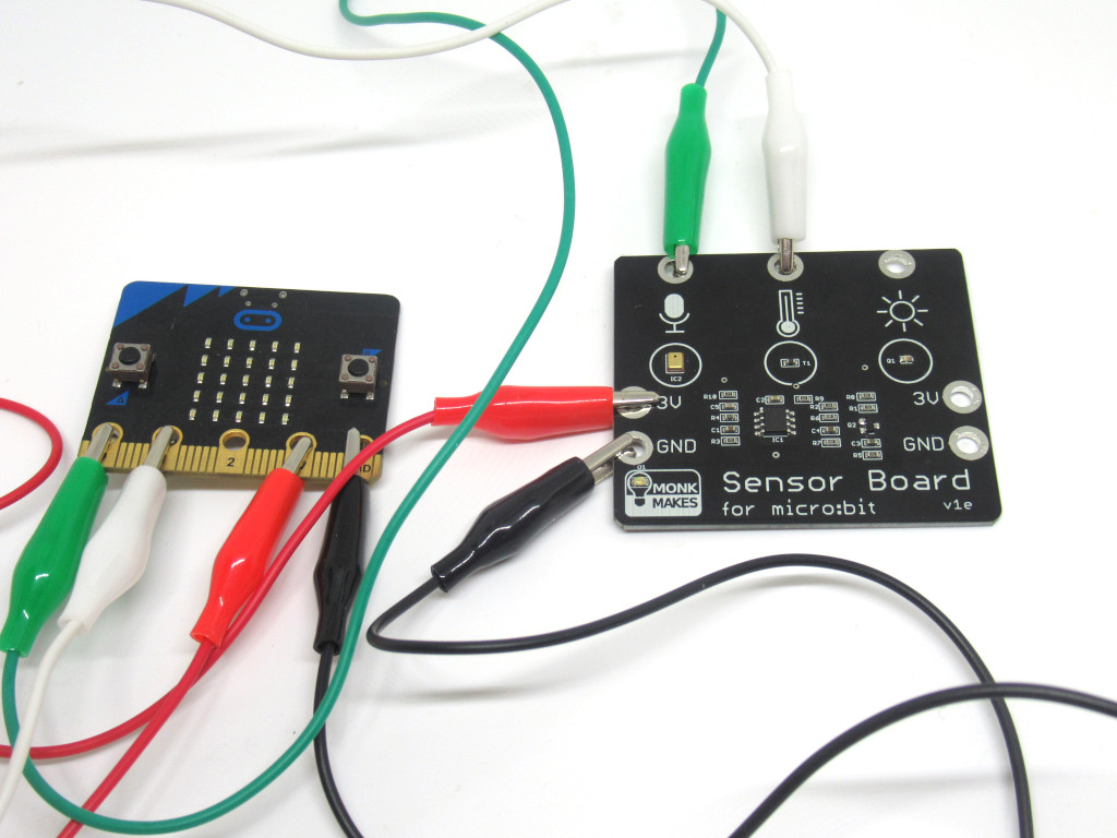
Attach a alligator clip from Temperature on the sensor board to P1 on the micro:bit
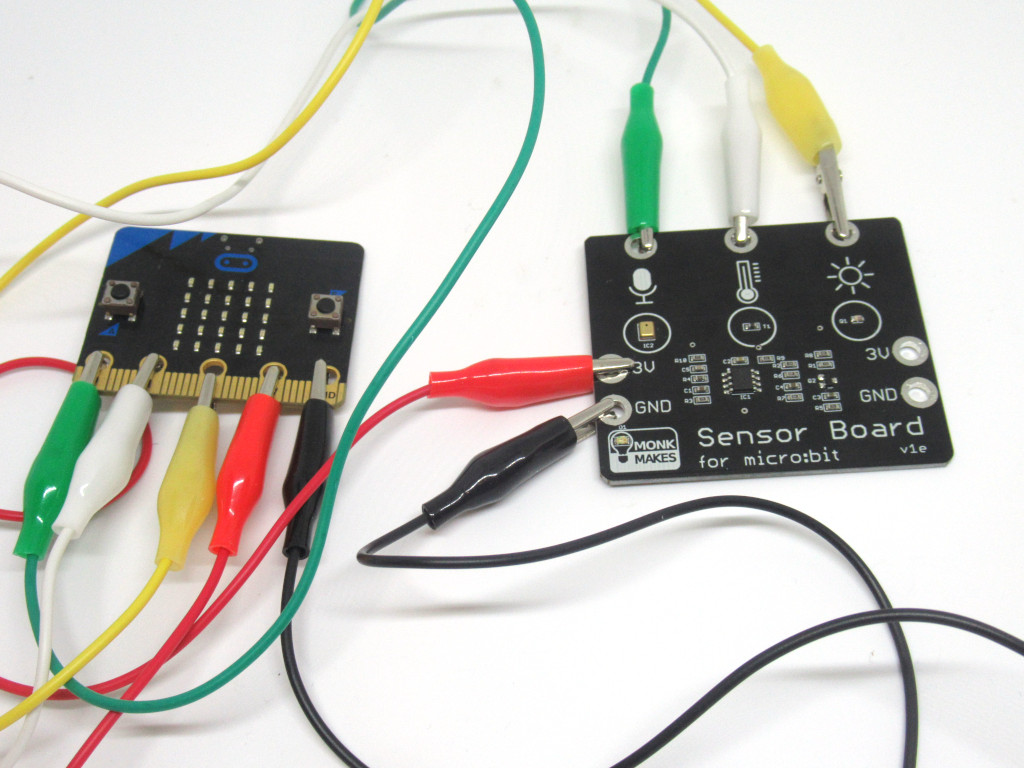
Attach an alligator clip from Light on the sensor board to P2 on the micro:bit
basic.forever(function () {
    led.plotBarGraph(
    pins.analogReadPin(AnalogPin.P0) - 511,
    512
    )
})
Open up the MakeCode editor
Click on 'New Project'
Add this code to the Javascript interface in MakeCode editor.
Jump to the Step 11 to upload this code to the micro:bit.
let reading = 0
let temp_c = 0
basic.forever(function () {
    reading = pins.analogReadPin(AnalogPin.P1)
    temp_c = Math.idiv(reading * 75, 1000) - 14
    basic.showNumber(temp_c)
    basic.pause(500)
})
Temperature readings in Degree Celsius will be displayed on the micro:bit's LED matrix.
Replace the existing code with the following in the Javascript interface.
Jump to the Step 11 to upload the code to the micro:bit.
basic.forever(function () {
    led.plotBarGraph(
    pins.analogReadPin(AnalogPin.P2),
    100
    )
})
Replace the existing code with the following in the Javascript interface.
Jump to the Step 11 for instructions on uploading the code to the micro:bit.
Here is an example of using the Sensor Board to display a bargraph to indicate the light level. Cover your finger over the light sensor to decrease the light level, the bargraph should have less LEDs lighting up. Shine a flashlight on it to increase its light level and the bargraph will light up accordingly!
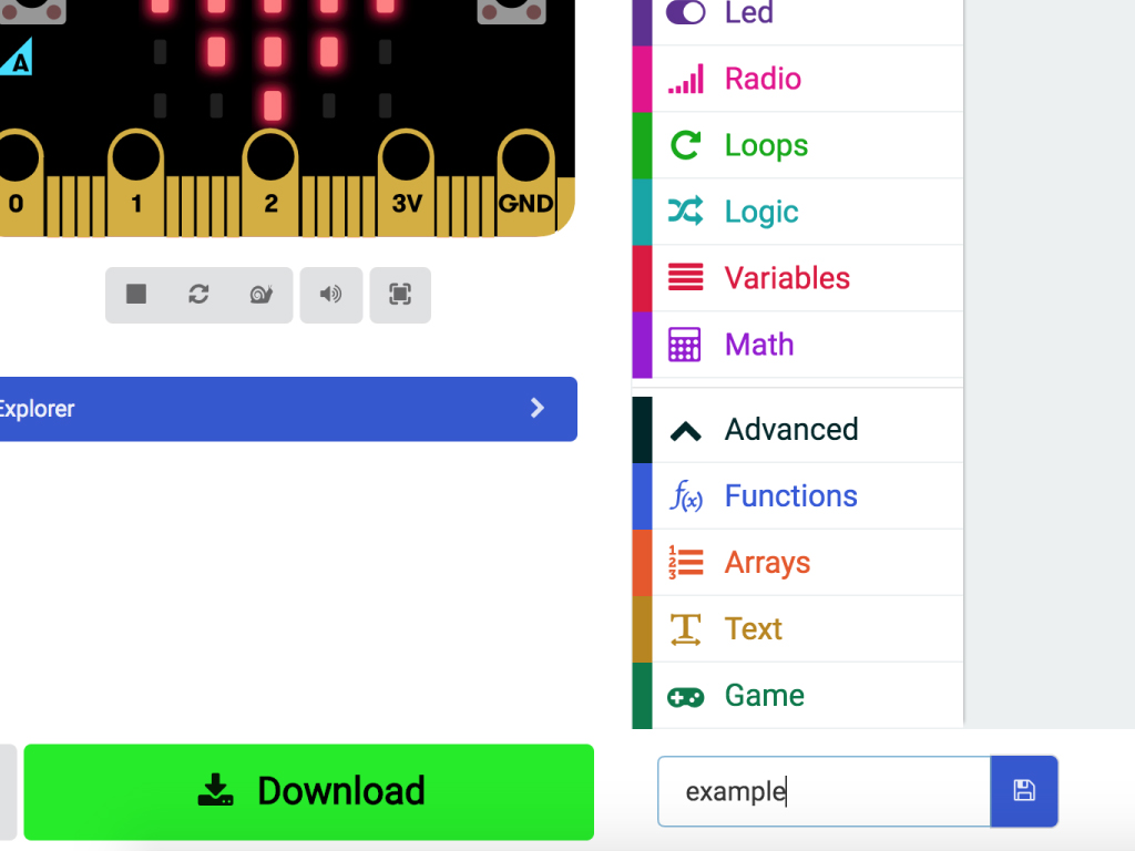
Click the download button in the bottom left corner of the screen. This will download a hex file (computer program file) which the micro:bit can read.
Next, plug in your micro:bit, this will reveal a USB on your computer
Lastly copy across the downloaded file to the micro:bit by dragging and dropping it into the MICRO:BIT drive. The micro:bit will flash as the code is being uploaded. Once done, unplug the micro:bit.
from microbit import *

while True:
    sleep(25)
    pin0reading = pin0.read_analog() # sound - blue line
    pin1reading = pin1.read_analog() # temperature - green line
    pin2reading = pin2.read_analog() # light - orange line
    print((pin0reading, ((pin1reading-400)*5), pin2reading))
Alternatively, the Sensor Board can also be programmed in Micropython by using the MU editor. This code will display a graph with all three readings in real-time.
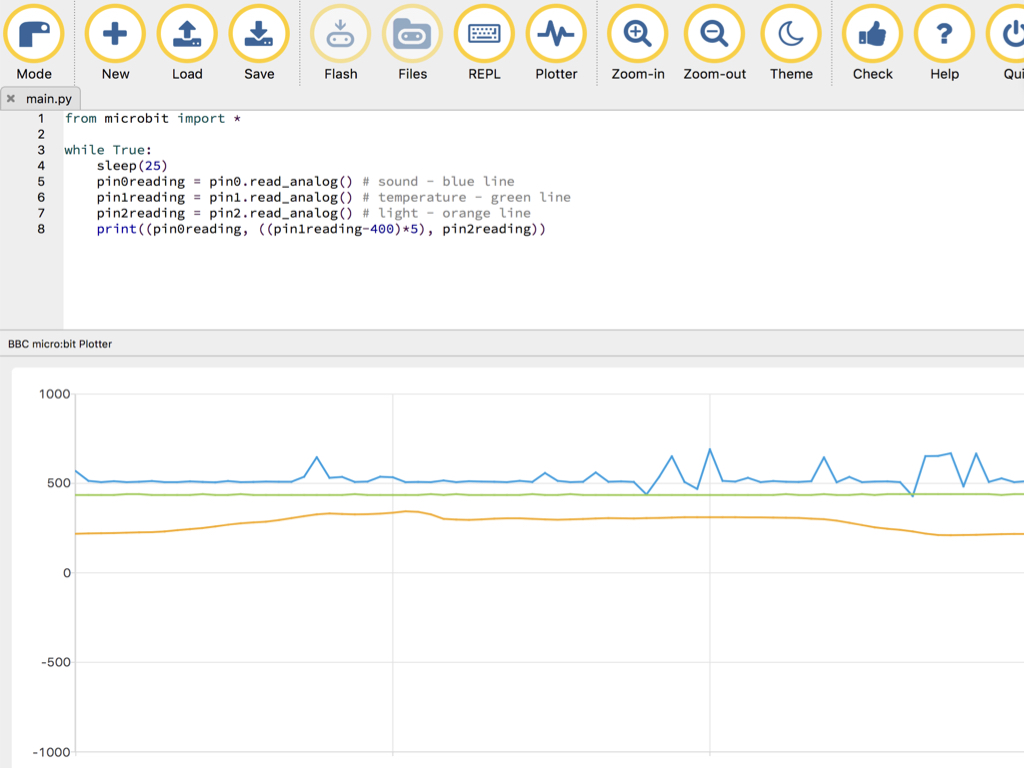
Click on the 'Plotter' icon up the top on the MU Editor interface.
Clap your hands or tap the table next to the sensor board. The blue line corresponding to the analog reading of the sound will change accordingly.
Shine a torch on the sensor board, near the light sensor, and the value of the orange line will increase.