Get Started With the EagLED
Familiarise yourself with the EagLED and its components
Written By: Cherie Tan
Difficulty
Easy
Steps
15
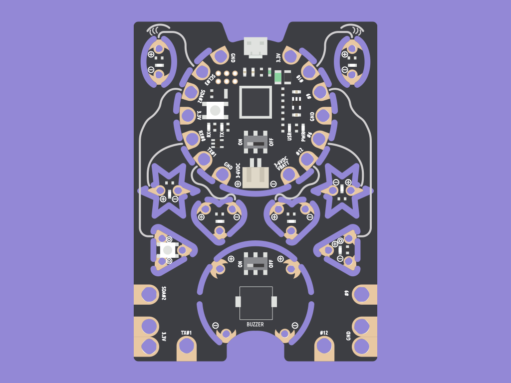
The EagLED is a beginner-friendly and fully Arduino-compatible micro-controller packed with e-textile compatible LEDs, a light sensor, pushbutton switch, and a buzzer module. It won't snag on your garments either, so they can easily be used for wearable or e-textile projects.
In this guide, we will take a closer look at the various parts of the EagLED as well as how you can set it up to be programmed using the Arduino IDE.
Complete this guide to get up to speed and start creating with the EagLED!
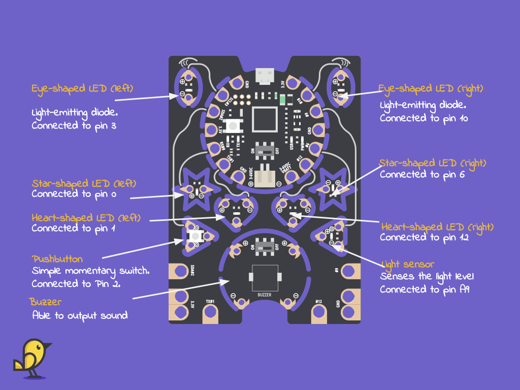
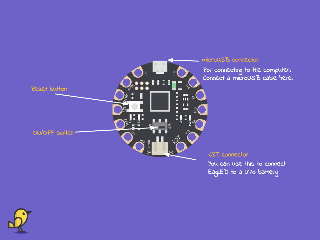
An overview of the EagLED:
There are LEDs and a pushbutton connected to digital pins
A light sensor connected to an analog pin
A buzzer module
SDA and SCL sew tabs
A microUSB connector
A JST connector
A SPST ON/OFF switch
A reset button
There are LEDs and a pushbutton connected to digital pins
A light sensor connected to an analog pin
A buzzer module
SDA and SCL sew tabs
A microUSB connector
A JST connector
A SPST ON/OFF switch
A reset button
In this guide, we'll take a closer look at some of these components.
This is EagLED Version 1.2, where the coin cell battery holder has been replaced with a buzzer module. If you have used Version 1.0, you will also notice that with Version 1.2, the colour of the entire board has been changed from white to black.
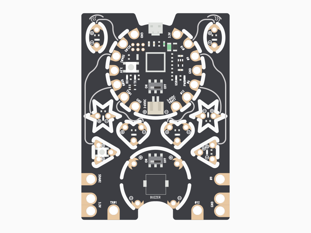
Take a look at the front side of the EagLED.
You'll notice the shapes that can be snipped out with a pair of cutters.
These are easily separable and sewn with conductive thread to make wearable electronics.
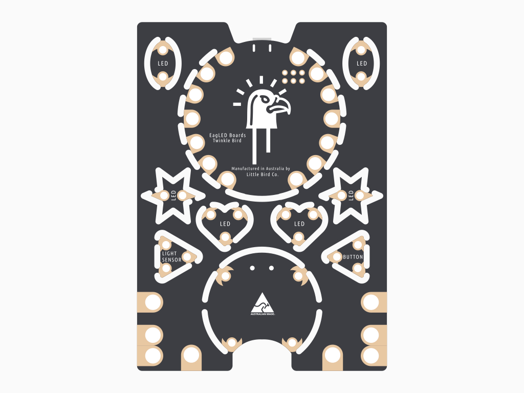
Flip it over and on the back side, you will see the labels:
LED
LIGHT SENSOR
BUTTON
Manufactured in Australia by Little Bird Co
LED
LIGHT SENSOR
BUTTON
Manufactured in Australia by Little Bird Co
There are four indicator LEDs on the main board. They are: TX, RX, PWR and USR.
RX stands for Receiving pin and is used for serial communication. Whenever the EagLED receives data serially, the LED connected to RX pin will blink.
TX stands for Transmitting pin and is also used for serial communication. Whenever it sends data serially, the LED connected to TX pin will blink.
PWR - This is the indicator light signifying that the board is powered.
USR - This is a user-controlled LED, and it can be accessed as Pin 7 in an Arduino sketch.
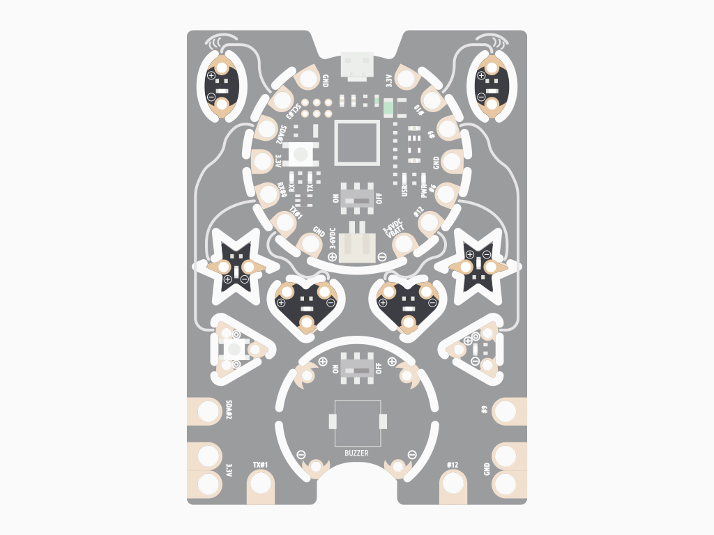
As you might notice, there are six tiny boards that have built-in LEDs.
Each of these boards have either two or three sewing tab pads.
By default when they are not snipped out, the LEDs can be programmed using the Arduino IDE with these pins:
left eye - Pin 3
right eye - Pin 10
left star - Pin 0
right star - Pin 6
left heart - Pin 1
right heart - Pin 12
left eye - Pin 3
right eye - Pin 10
left star - Pin 0
right star - Pin 6
left heart - Pin 1
right heart - Pin 12
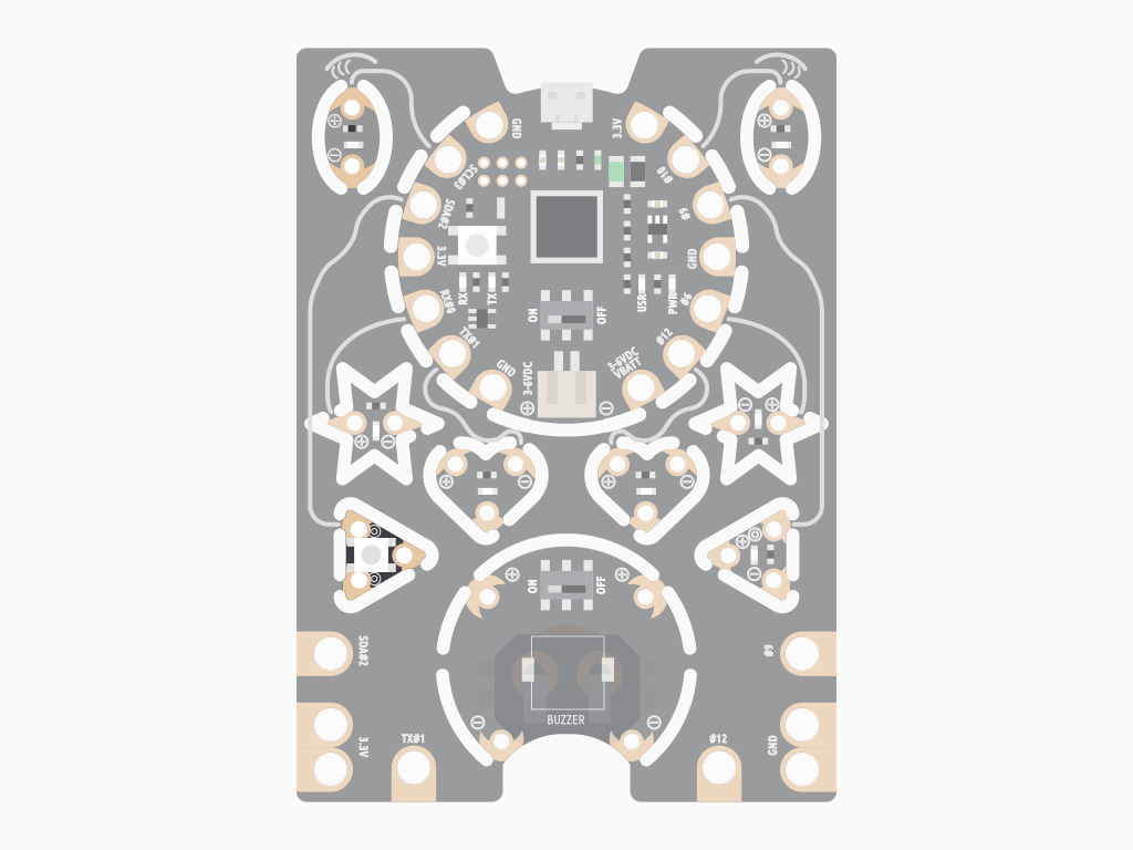
One of the triangular-shaped board has a built-in button.
This board also has three sewing tab pads.
The button can be programmed using Pin 2 in the Arduino IDE.
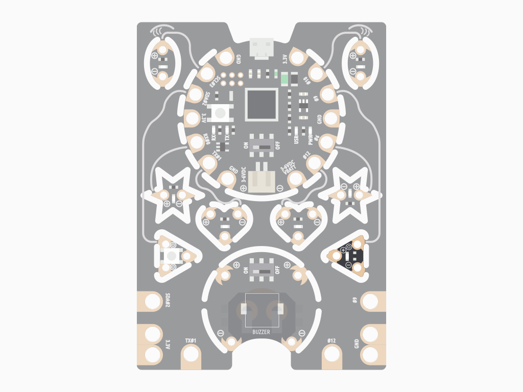
The other triangular-shaped board has a built-in light sensor.
This board has three sewing tab pads.
The light sensor can be programmed by using Analog Pin 9 in the Arduino IDE.
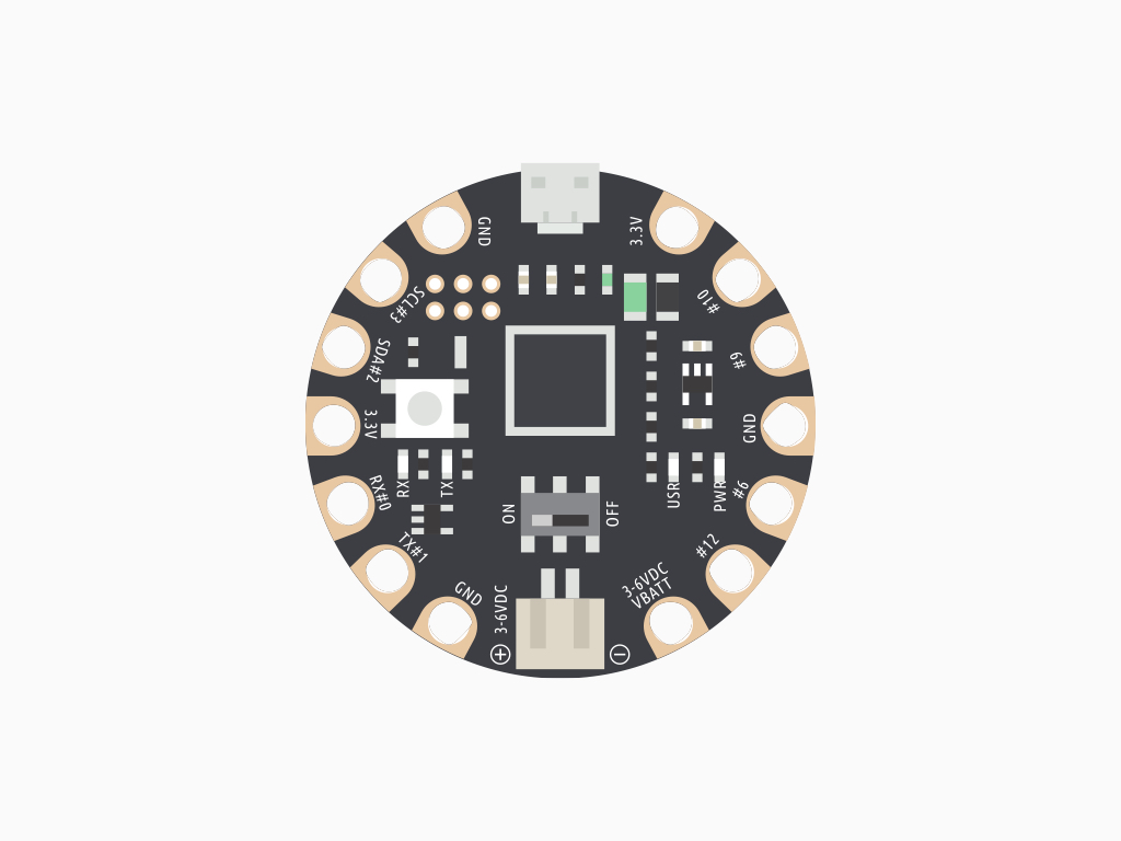
On the main board, you'll see the following pins:
+
-
GND
3.3V
SCL#3
SDA#2
RX#0
TX#1
VBATT
#12
#6
#9
#10
+
-
GND
3.3V
SCL#3
SDA#2
RX#0
TX#1
VBATT
#12
#6
#9
#10
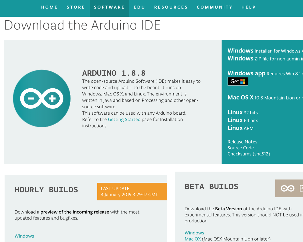
To get started with programming the EagLED, you'll need the Arduino IDE. Head to the Arduino Downloads page to download the software for your operating system.
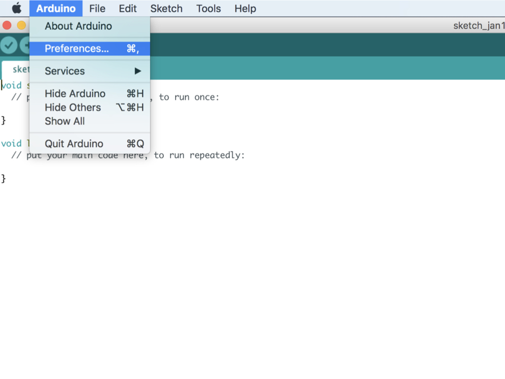
After downloading and installing the software, open up the Arduino IDE. To add board support for our products, start Arduino and open the Preferences window.
On Windows on Linux, Click (File > Preferences)
On a Mac, click on the (Arduino Menu > Preferences)
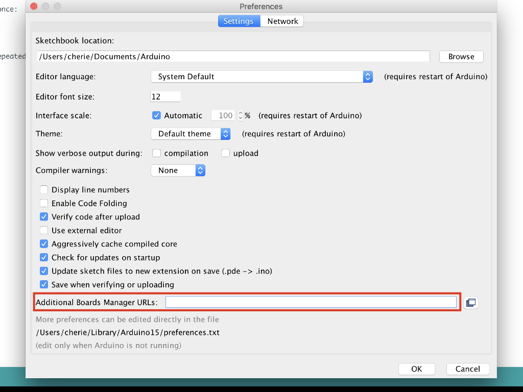
Copy and paste the following URL into the 'Additional Boards Manager URLs' input field: https://raw.githubusercontent.com/littlebirdelectronics/Arduino_Boards/master/IDE_Board_Manager/package_littlebird_index.json
Press the 'OK' button
If there is already an URL from another manufacturer in that field, click the button at the right end of the field. This will open an editing window allowing you to paste the above URL onto a new line.
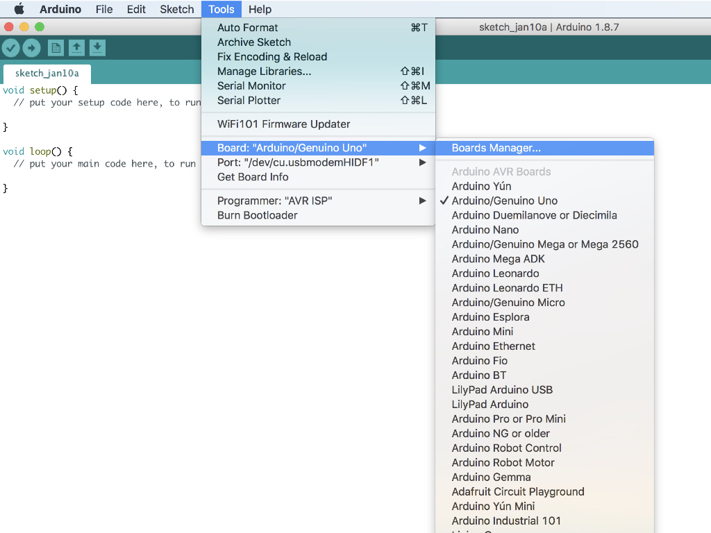
Now open up the Boards Manager by clicking on Tools > Board
Scroll to the top of the board list, and select Boards Manager.
If you type "Little Bird" (without quotes) into the "filter your search" field, you will see options to install Little Bird's board files.
Click the "Install" button that appears.
Once installed, the boards will appear at the bottom of the board list. Select 'Little Bird EagLED'. Now you can go on to program the EagLED with the Arduino IDE!
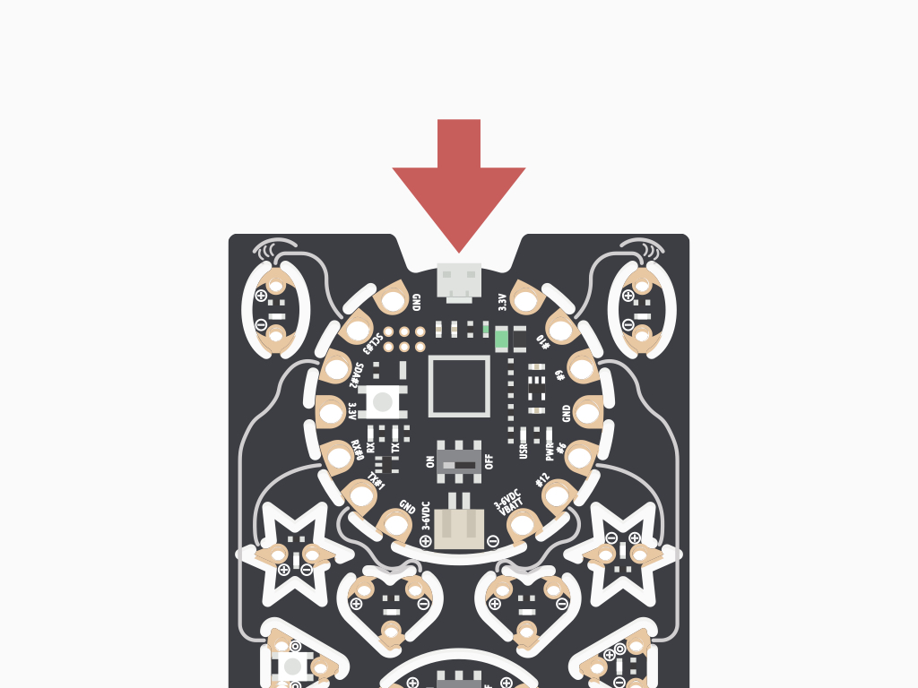
Connect your EagLED to your computer using the appropriate USB connector such as a micro USB cable.
Connect one end to the microUSB port on the EagLED
Connect the other end of the cable to a USB port on your computer
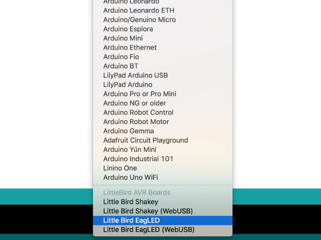
Go to Tools > Board: ...
Select 'Little Bird EagLED'
Go to Tools > Port
Select the port that your EagLED is on. This will be different depending on your computer.
On Windows your Arduino will appear as a COM port
On Windows your Arduino will appear as a COM port
On macOS and Linux it will appear as a /dev/cu.usbmodemXXXXX.
