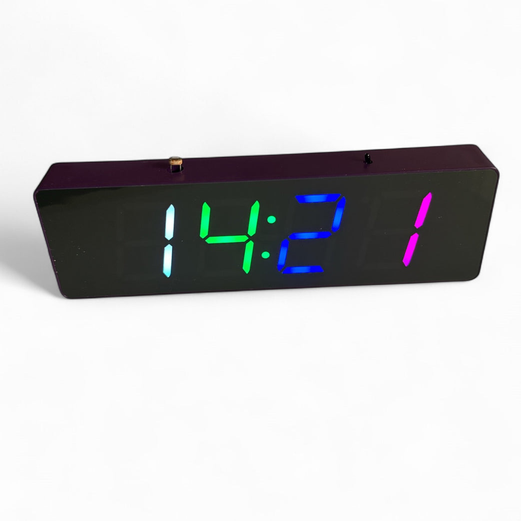
DIY LED Clock Kit
Soldering guide for DIY LED Clock Kit
Written By: Marcus Schappi
Difficulty
Easy
Steps
8
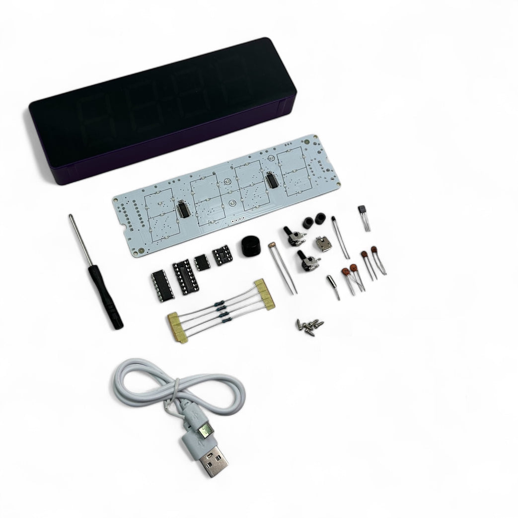
Acrylic LED display case
Main PCB (with silkscreen component outlines)
4× 7-segment LED displays
ICs & Sockets
4 x Resistors
2 x Capacitors 100uf
2 x Capacitors 22pf
1 x Diodes
1 x Transistors
2 x Capacitors 100uf
2 x Capacitors 22pf
1 x Diodes
1 x Transistors
2 x Push buttons
Micro USB port and cable for power
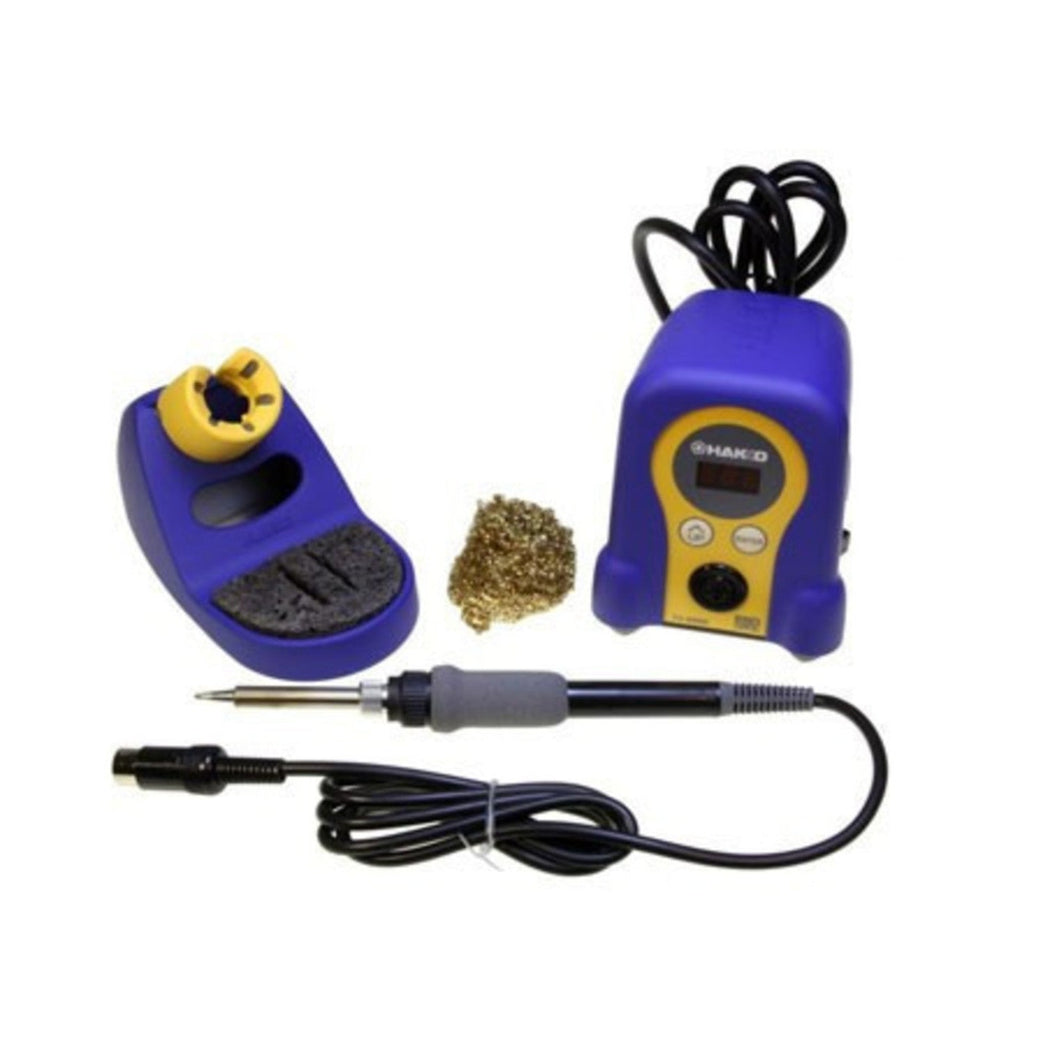
Screwdriver
This kit does NOT come with the CR1220 battery holder (for RTC backup) as the enclosure would not comply with Australian Standards.
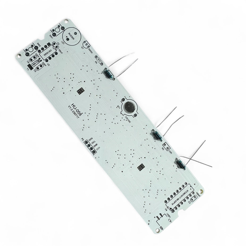
Insert resistors into the correct places.
Bend leads, solder, and clip excess.
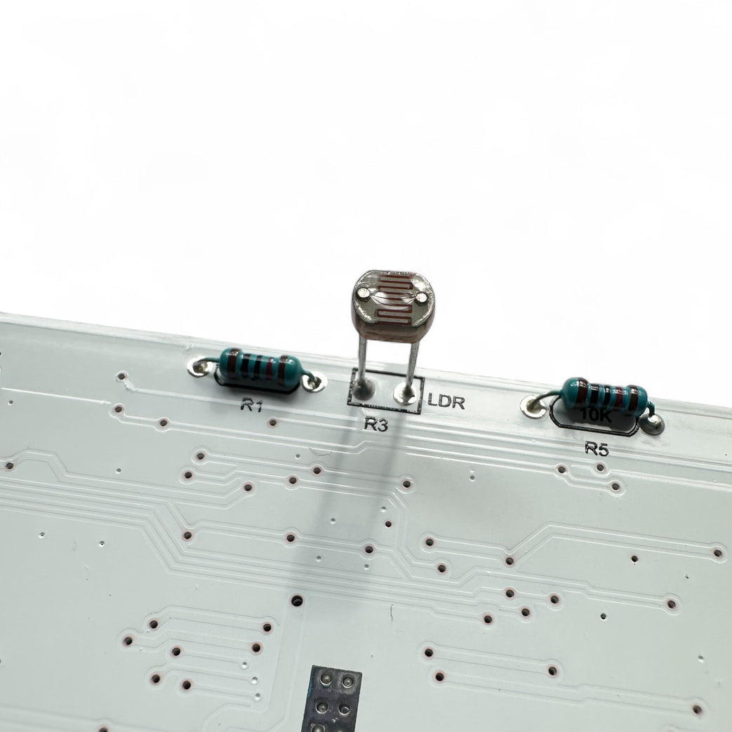
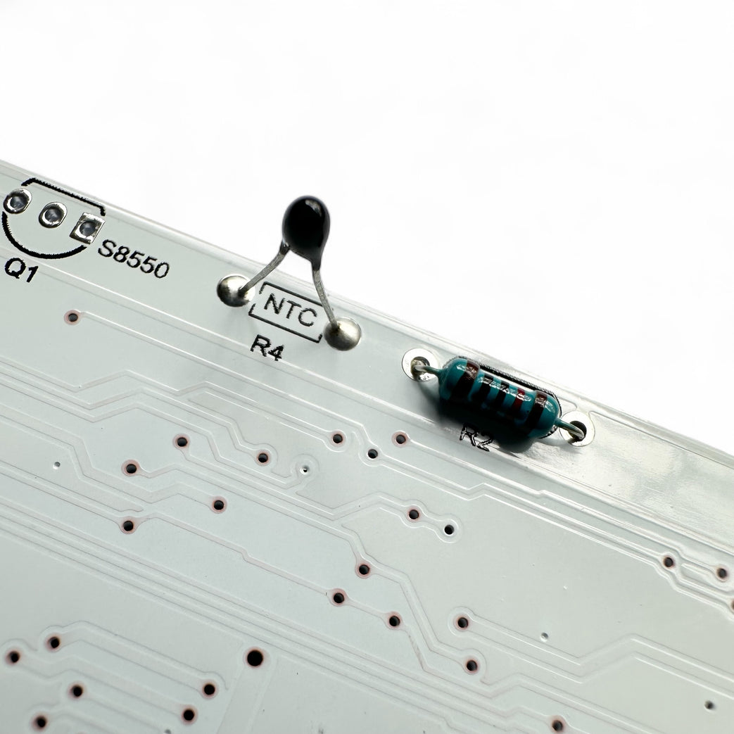
Make sure that these stand about 8mm from the PCB as it needs to pass through the top of the case to sense light and temperature.
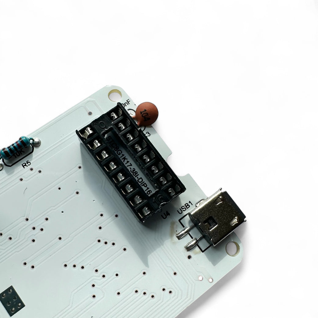
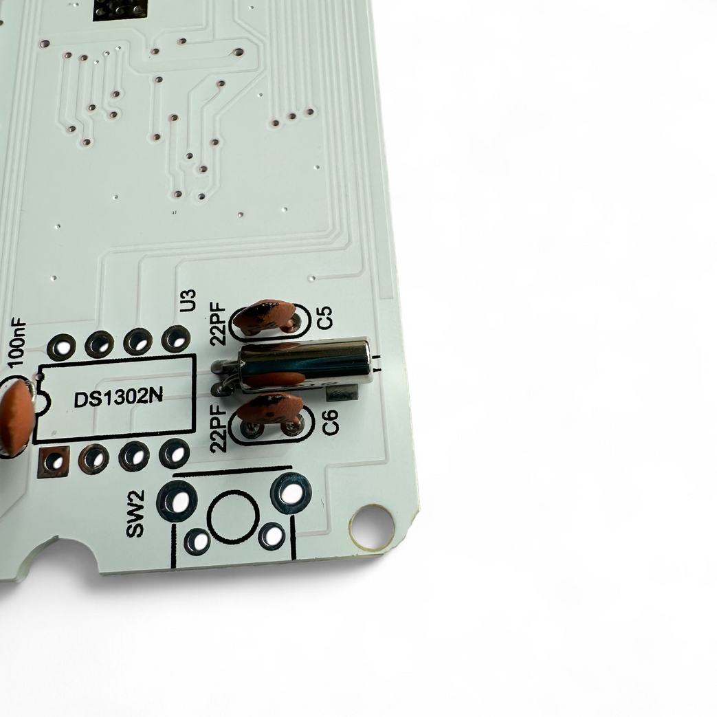
Insert small round brown caps (22 and 104).
They are not polarised so can go either way.
Insert sockets for ICs (don't install ICs yet).
Ensure notch in socket matches the notch on PCB silkscreen.
Solder all pins cleanly.
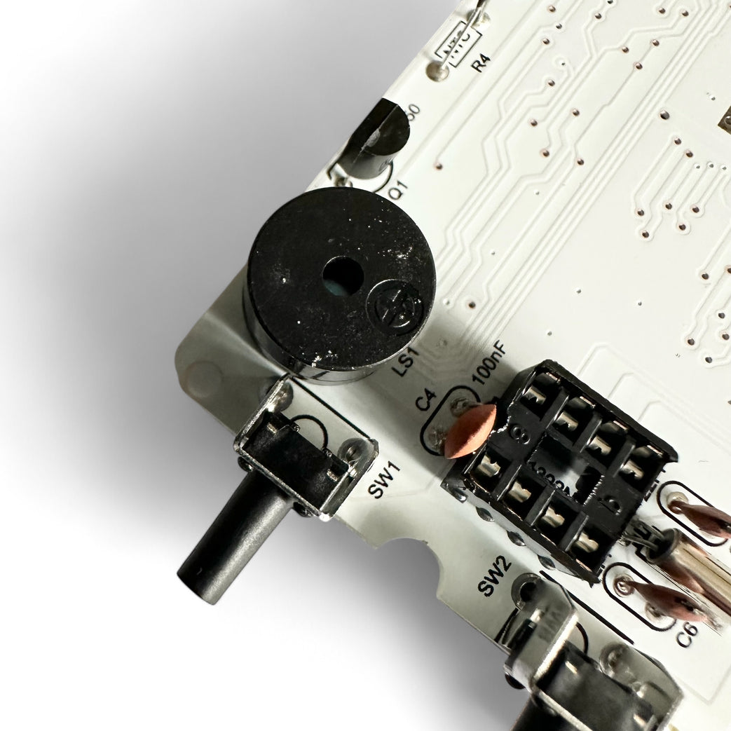
The underside of the buzzer has the + and - labelled.
Make sue it matches up with the PCB
Make sue it matches up with the PCB