Digital Inputs with Raspberry Pi
Learn how to read digital inputs with the GPIO Zero Library
Written By: Cherie Tan
Difficulty
Easy
Steps
12
One of the most useful features of the Raspberry Pi is its 40-pin GPIO header, which makes it easy for connecting to electronic components. Controlling the GPIO ports involves complex code, but this is already written for you and made easy to use with the GPIO Zero Library.
In this guide, we'll show you how to get started with reading digital inputs by reading the values of a pushbutton with the Raspberry Pi 3 Model B+ and GPIO Zero Library.
Complete this guide to gain a basic understanding of digital inputs with the Raspberry Pi.
In this guide, we'll show you how to get started with reading digital inputs by reading the values of a pushbutton with the Raspberry Pi 3 Model B+ and GPIO Zero Library.
Complete this guide to gain a basic understanding of digital inputs with the Raspberry Pi.
Physical computing is one of the most engaging ways to learn programming. From flashing lights to building an Internet of Things device, the Raspberry Pi's General Purpose Input Output (GPIO) pins makes this process accessible for beginners.
What is Physical Computing, though? One way to think of it: physical computing is about creating a conversation between the physical world and the computer through the process of transduction, or the conversion of one form of energy into another.
What is Physical Computing, though? One way to think of it: physical computing is about creating a conversation between the physical world and the computer through the process of transduction, or the conversion of one form of energy into another.
Getting started with programming electronics used to require many more lines of code. With the GPIO Zero library, all the boilerplate code has already been written for you, so you can jump right into it and focus on controlling the physical devices.
The GPIO Zero module actually uses RPI.GPIO, another Python library which enables the control of GPIO pins. However, the GPIO Zero Library makes it even more accessible and intuitive.
When trying to sense activity in the physical world using the Raspberry Pi, you may only need to know whether something is true or false. For instance, has the button been pushed or not?
When we only care about the difference between two possible states, we can determine what we need to know with a digital input. For example, a push button switch is a digital sensor that can be in one of two states: pushed or not pushed, HIGH or LOW, '1' or '0'.
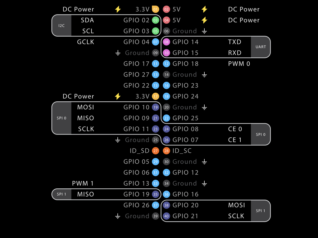
In this guide, we're using the Raspberry Pi 3B+. Before diving into programming with the GPIO Zero library, let's take a closer look at the pins on the Raspberry Pi. In the diagram, you'll notice that there are plenty of 'GPIO' pins. These GPIO pins are integrated into the circuit board of the Raspberry Pi. As noted before, their behaviour can be controlled to interface with the physical world whether by reading data from sensors, or using components such as LEDs and displays.
Older models of the Raspberry Pi had 26 GPIO pins, while the newer models have 40.
If you are using a different model of Raspberry Pi, please note that its pinout may differ.
Let's start with the power pins. The Raspberry Pi 3B+ can provide both 5V (pins 2 and 4) and 3.3V power (pins 1 and 17)
Ground are the pins you use to ground your devices. They are all connected to the same line, so you can use any of them to ground your devices.
A large number of sensors and other peripherals can be attached to the Raspberry Pi through the I2C (Inter-Integrated Circuit) protocol. For these electronic devices to communicate with one another, they need to speak the same language; in electronics, these languages are called communication protocols.
The I2C communication protocol is a commonly used standard that enables one chip to talk to another. In this instance, it lets the Raspberry Pi communicate with a variety of other I2C capable chips or modules.
To physically connect peripherals to the Raspberry Pi, we need to use only four wires: Ground, VCC, SDA, and SCL.
SDA (Serial Data Line) can be accessed on Pin 3
SCL (Serial Clock Line) can be accessed on Pin 5
SPI known as Serial Peripheral Interface is another communication protocol that is similar to I2C. However, there are several differences:
It operates at a higher speed and is often used for devices that require continuous transfer of large amounts of data i.e. displays and audio. That is to say, it is good for high data rate full-duplex connections, the simultaneous sending and receiving of data.
There is one master on the bus, this role is usually taken by the microcontroller and in this case, the Raspberry Pi. The 'slave' devices may be the sensors that are attached, and they require the use of at least six pins for communication. Aside from VCC and Ground, it requires another 4 pins for communication:
MOSI (master-out-slave-in) - Sends information from the 'Master' device to 'Slave' device, and can be accessed on Pin 19 (SPI0 bus) or Pin 38 (if using the SPI1 bus).
MISO (master-in-slave-out) - Sends information in the reverse direction, and can be accessed on Pin 21 (SPI0 bus) or Pin 35 (if using SPI1 bus)
SCLK (clock) - Line for the clock signal, and can be accessed on Pin 23 (SPI0 bus) or Pin 40 (if using the SPI1 bus)
CS (chip select) - Line for the 'master' device to select which 'slave' device to send data to, and can be accessed on Pin 24 (CE 0) and Pin 26 (CE 1)
SCLK, MISO, and MOSI lines can be shared among many slaves, but each slave requires its individual CS line.
UART also known as universal asynchronous receiver-transmitter, is used for serial communication and allows the Raspberry Pi to communicate with other serial devices.
It uses the RX line and TX line, as well as a fixed baudrate. Common devices that use UART include MIDI interfaces, thermal printers, GPS modules, etc.
The UART system can be accessed on pins 8 (TXD) and 10 (RXD).
It uses the RX line and TX line, as well as a fixed baudrate. Common devices that use UART include MIDI interfaces, thermal printers, GPS modules, etc.
The UART system can be accessed on pins 8 (TXD) and 10 (RXD).
Finally, you may notice that there is also a pair of odd pins, ID_SD and ID_SC.
These must only be used for attaching a compatible ID EEPROM. EEPROMS are a type of non-volatile memory, and are used by Raspberry Pi HATS.
These must only be used for attaching a compatible ID EEPROM. EEPROMS are a type of non-volatile memory, and are used by Raspberry Pi HATS.
Now that you're familiar with the pins on the Raspberry Pi 3 Model B+, we'll now create a simple circuit to begin using digital inputs with the GPIO Zero Library.
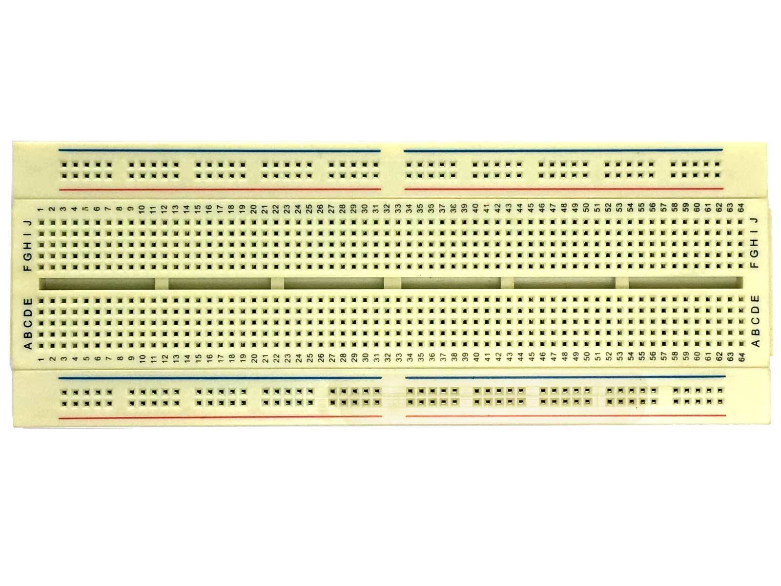
In this tutorial we're going to build the circuit by using a solderless breadboard for prototyping.
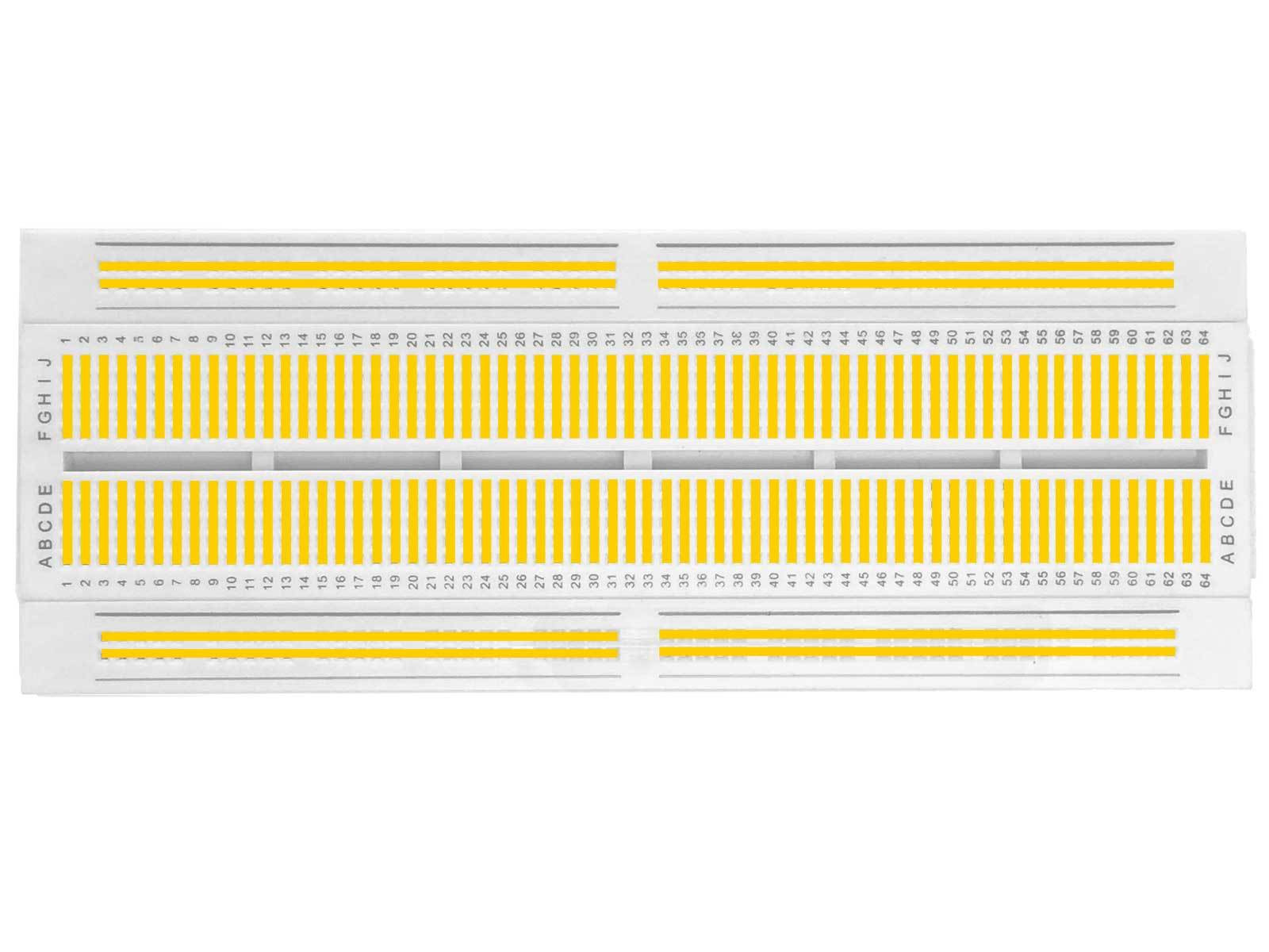
A modern solderless breadboard consists of a perforated block of plastic with conductive spring clips under the perforations.
The holes in the breadboard are sometimes called tie points.

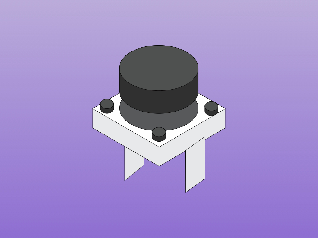
The momentary pushbutton we'll be using in this guide has two legs. When the button is pressed, there will be a connection between both legs and that completes an electric circuit, allowing electricity to flow. If not, the spring inside it retracts, and there is no connection between them.
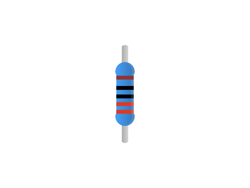
Resistors are generally used to protect electronic components by limiting the amount of current that flows through the circuit.
In this guide, we won't need to use an external resistor as the Raspberry Pi's GPIO pins have internal resistors that can be controlled from code.
Later, when we use the GPIO Zero library, it will use the Raspberry Pi's built-in resistor by default.
Later, when we use the GPIO Zero library, it will use the Raspberry Pi's built-in resistor by default.
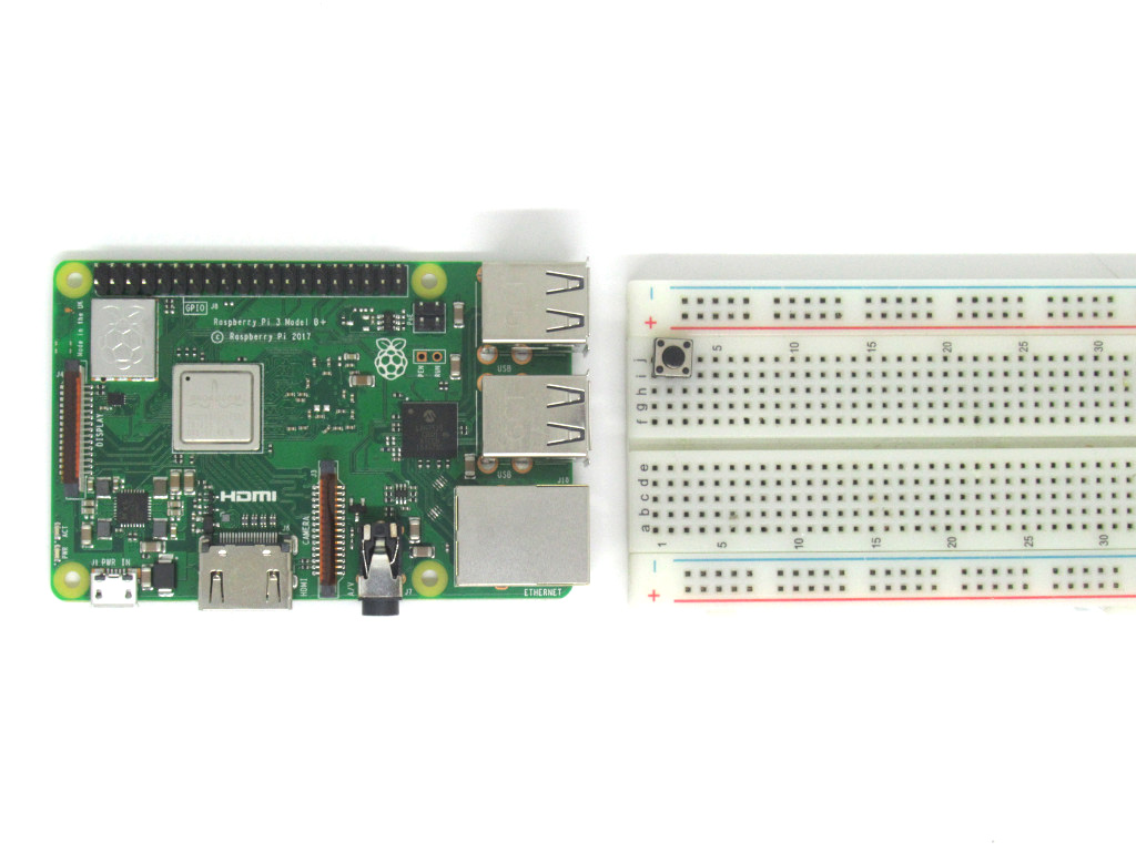
Insert the pushbutton into the breadboard between tie points J1 and J3.
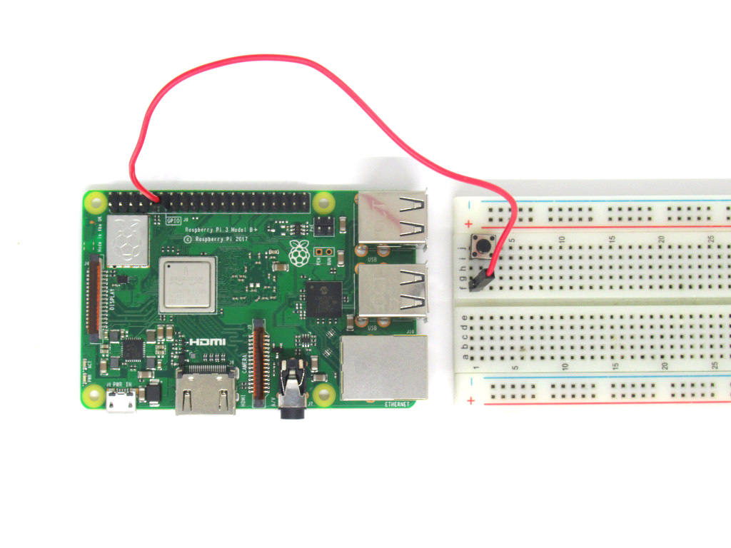
Connect a Red Jumperwire from tie point F1 to GPIO 17 on the Raspberry Pi.
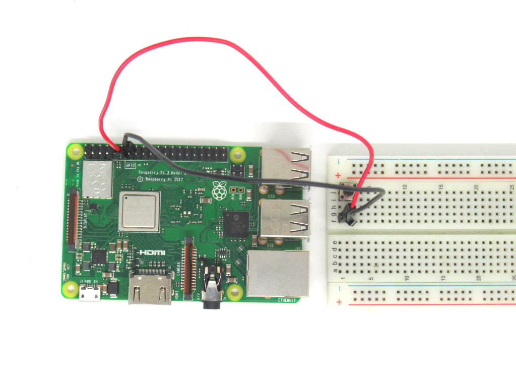
Connect a Black Jumperwire between tie point F3 and GND on the Raspberry Pi.
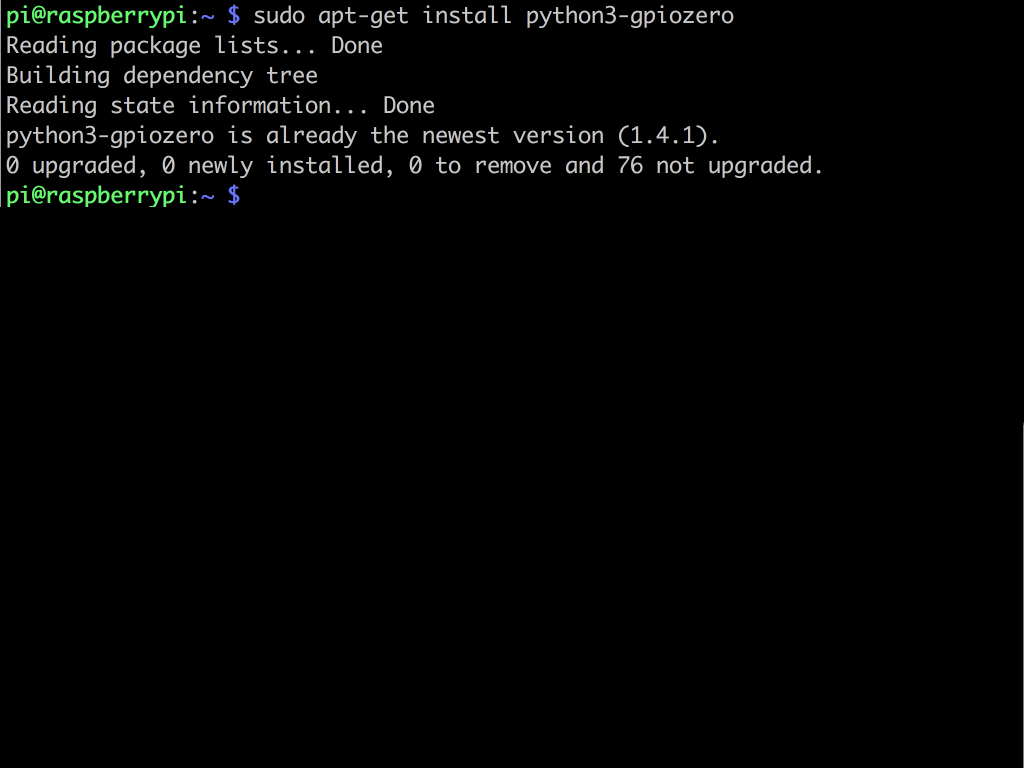
Then enter the following command: sudo apt-get install python3-gpiozero
Now that we have the Raspberry Pi hooked up to the breadboard and pushbutton, we will need to program it to read the pushbutton's values. Make sure the microSD card loaded with Raspbian is inserted into the Pi, then power it up with the appropriate power supply. If you do not have Raspbian set up, please check out our previous guide on getting started with the Raspberry Pi.
We will install GPIO Zero, the Python library which builds upon existing GPIO libraries such as RPI.GPIO, rPIO, and pigpio. It will simplify the process by reducing boilerplate code.
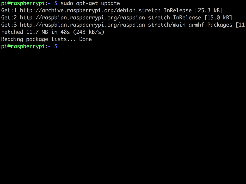
To do so, open a terminal window and enter the following: sudo apt-get update
To do so, open a terminal window and enter the following: sudo apt-get update
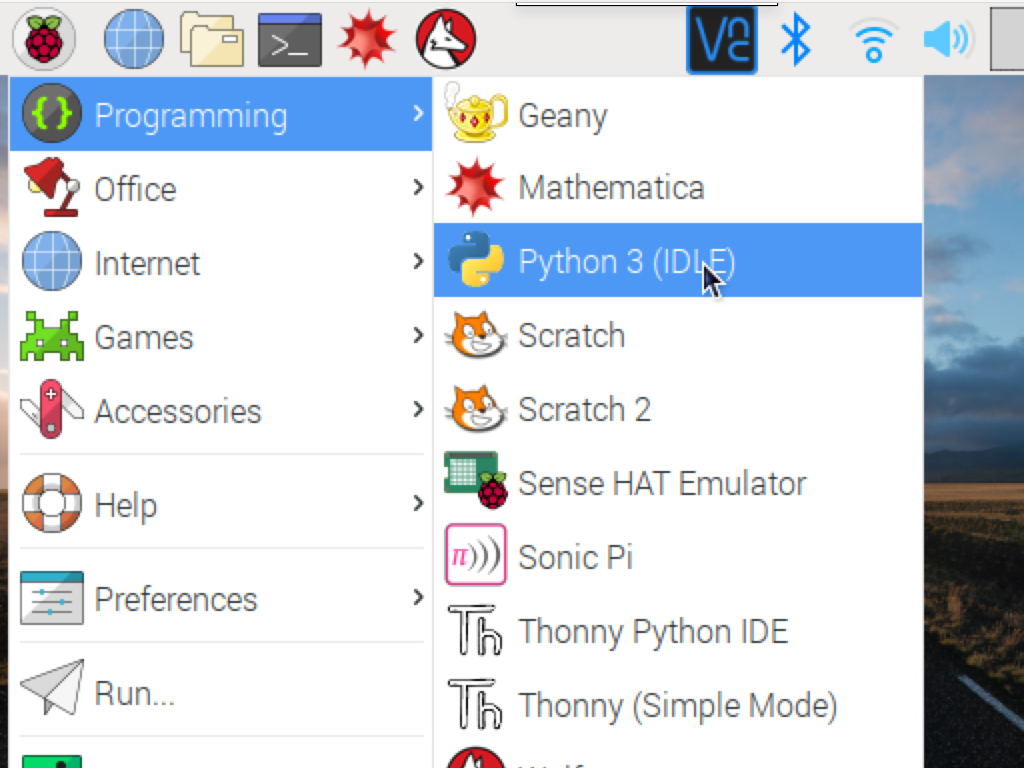
Click on the Raspberry Pi icon on the top left hand corner to access the main menu.
Click on Programming > Python 3 (IDLE).
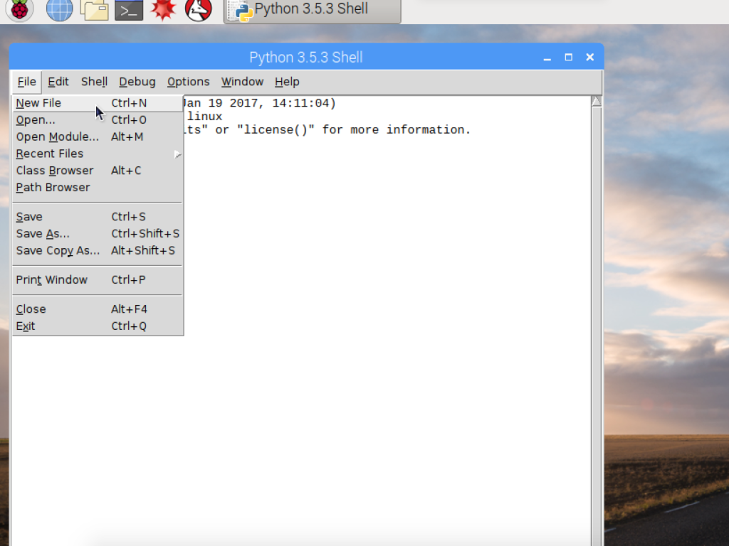
Now, create a new file by clicking File > New File.
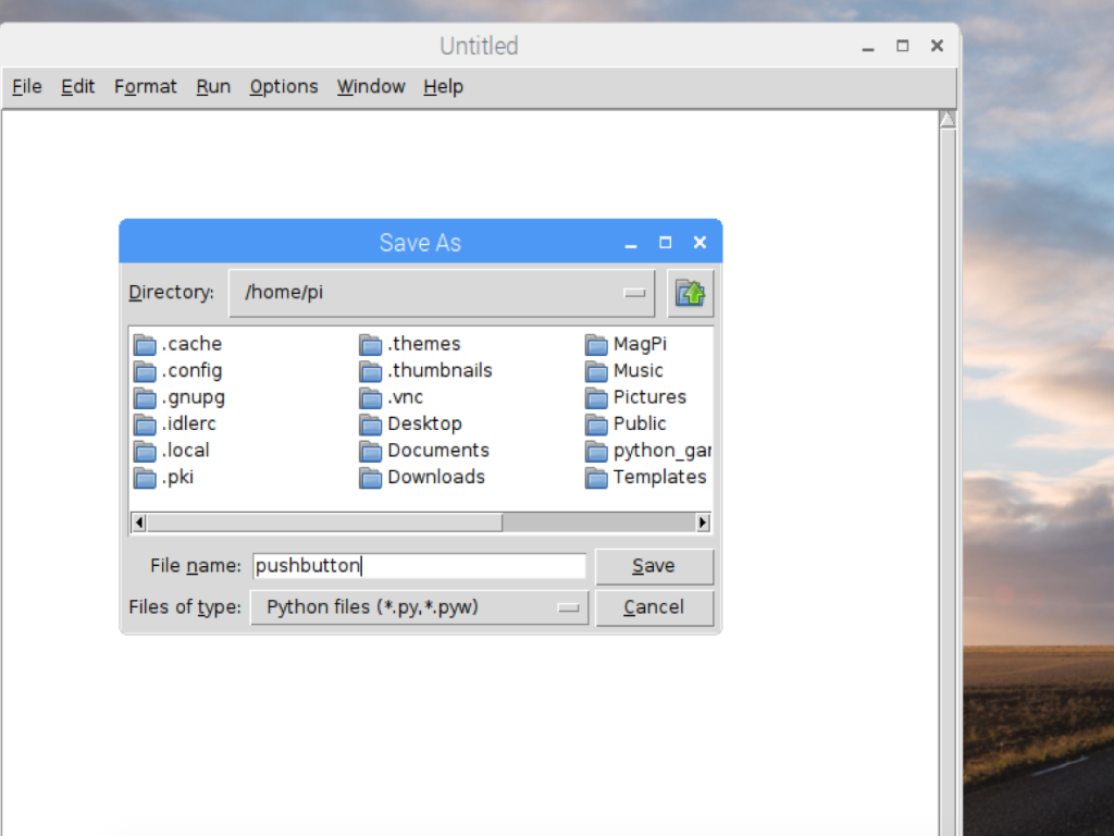
Next, save the file by clicking File > Save, and naming it pushbutton.py
from gpiozero import Button
button = Button(17)
while True:
        if button.is_pressed:
                print("Button is pressed")
        else:
                print("Button is not pressed")
Finally, a while loop is used to create a never-ending loop that will check whether the button has been pushed or not.
We'll now test the circuit with a simple Python program. Whenever the button is pushed, a message will be displayed on the screen.
Enter the following code into your Python file, then save and run it.
First, we import the Button class from GPIO Zero by using: from gpiozero import Button
Next, we assigned the button variable to GPIO 17 using the code:
button = Button(17)
button = Button(17)