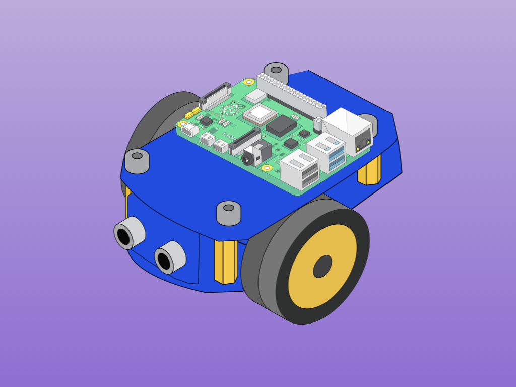
Two-wheeled Robot with Raspberry Pi 4
Build your own two-wheeled robotic car that can move forward, backwards, turn right and left
Written By: Marcus Schappi
Difficulty
Medium
Steps
22
Robots are all around us. They can be found building the products we use everyday, saving lives in surgical operations, exploring Mars, mowing our lawns or vacuuming our floors and in many more applications. While robotics is a broad field, it's easy to get started with the Raspberry Pi.
In this first of three guides, learn how to put together a super simple Raspberry Pi robot kit and start programming with Python.
Complete this guide to build your own two-wheeled robotic car that can move forwards, backwards, turn right and left!
In this first of three guides, learn how to put together a super simple Raspberry Pi robot kit and start programming with Python.
Complete this guide to build your own two-wheeled robotic car that can move forwards, backwards, turn right and left!
Robots are all around us. They can be found building the products we use everyday, saving lives in surgical operations, exploring Mars, mowing our lawns or vacuuming our floors and in many more applications. Get started with creating your own robot with the Raspberry Pi!
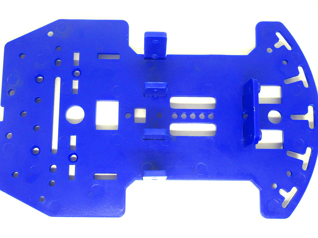
Aside from a Raspberry Pi, also used in this guide is our super accessible and versatile Robot Chassis with 2 wheels kit. The parts included in the kit will cover most of what is needed. Then you'll just need a motor driver controller, 4 x AA batteries, a powerbank, and jumper wires.
In this first of three guides, learn to build a two-wheeled robot from a super simple Raspberry Pi robot kit, where we will pre-program it to move with Python code. The robot will be able to move forwards, backwards, and turn.
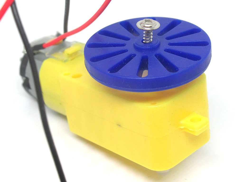
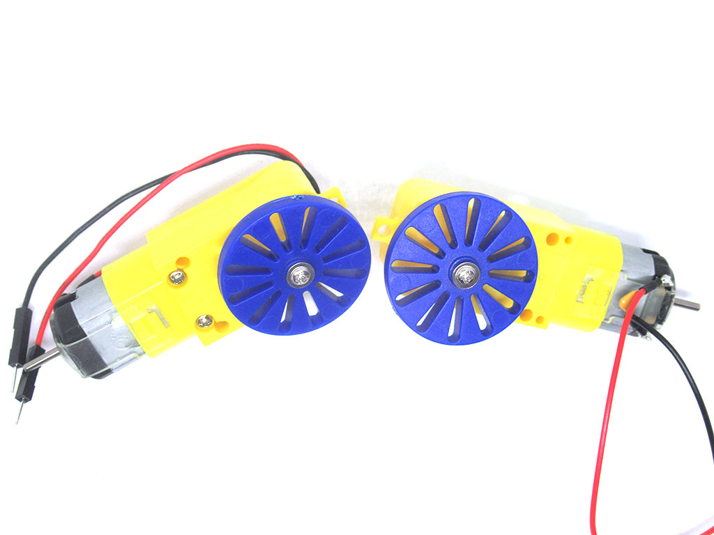
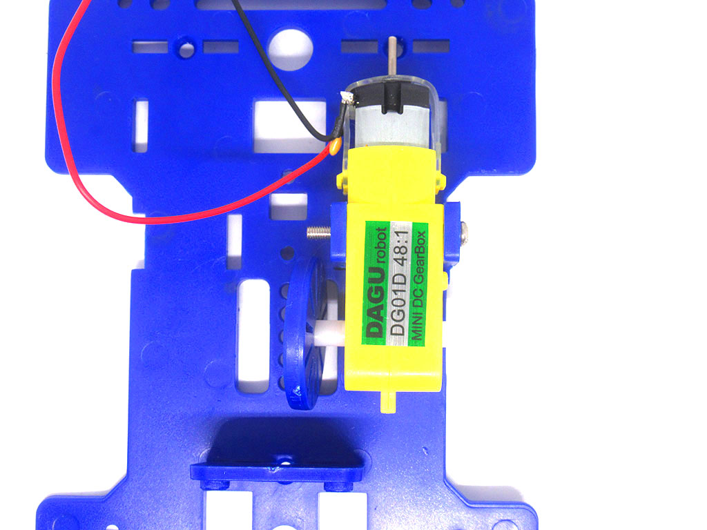
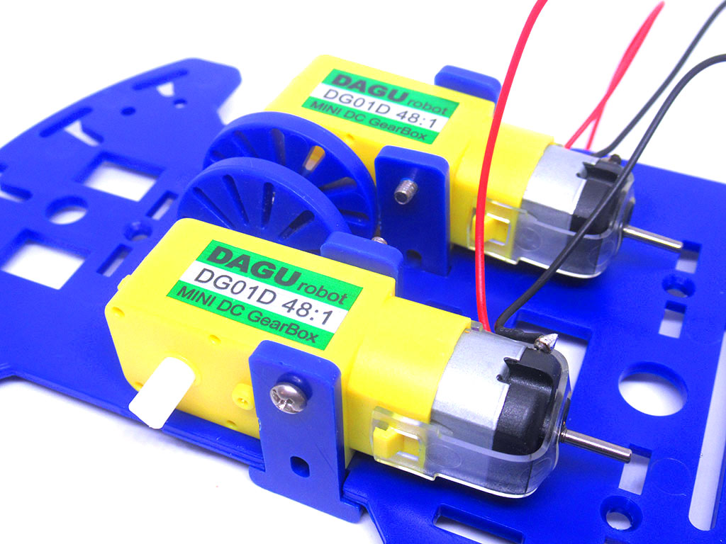
Connect a motor with one of the speed board holders with a M2.3*8 self-tapping screw.
Repeat the step with the other motor and speed board holder.
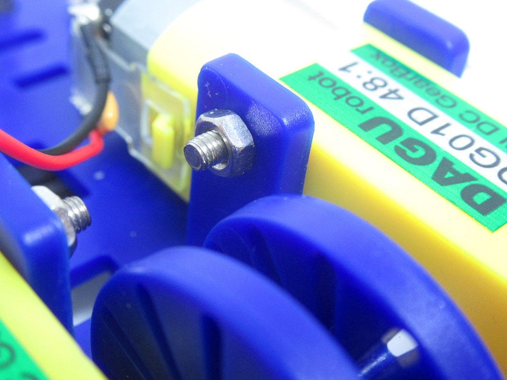
There are only two M2.3*8 self-tapping screws (with flange) in the kit.
Self-tapping screws are designed to cut their own hole as it is screwed into the material. A flange here refers to the circular flange under the head of the screw that acts like a washer, this distributes the load; these screws are designed for applications where vibrations can loosen fasteners. It makes sense why it is used to fasten the speed board holder to the motor, doesn't it?
Self-tapping screws are designed to cut their own hole as it is screwed into the material. A flange here refers to the circular flange under the head of the screw that acts like a washer, this distributes the load; these screws are designed for applications where vibrations can loosen fasteners. It makes sense why it is used to fasten the speed board holder to the motor, doesn't it?
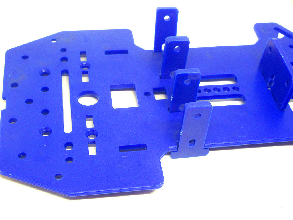
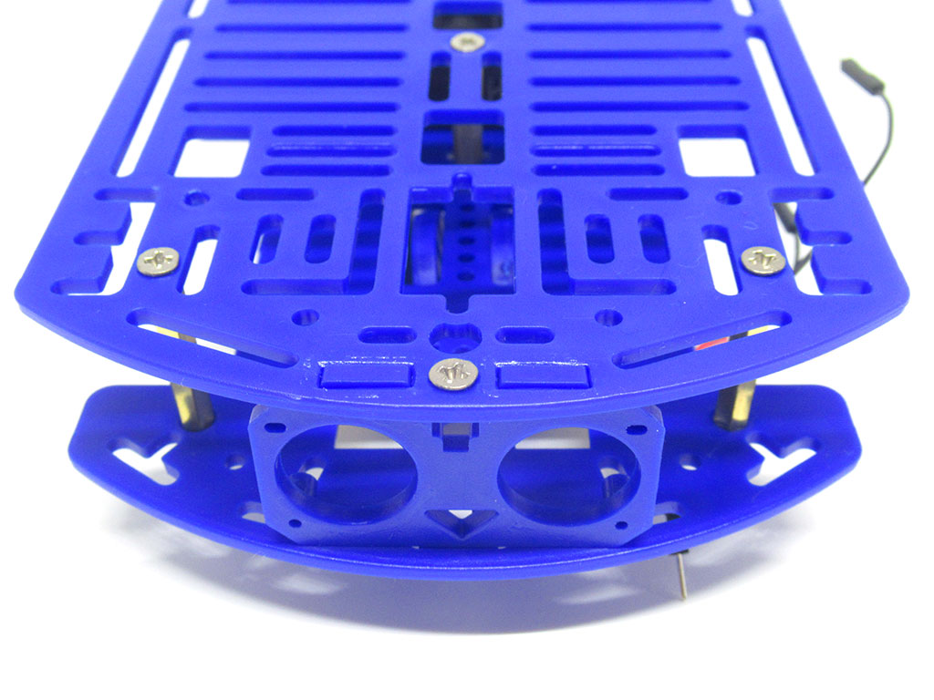
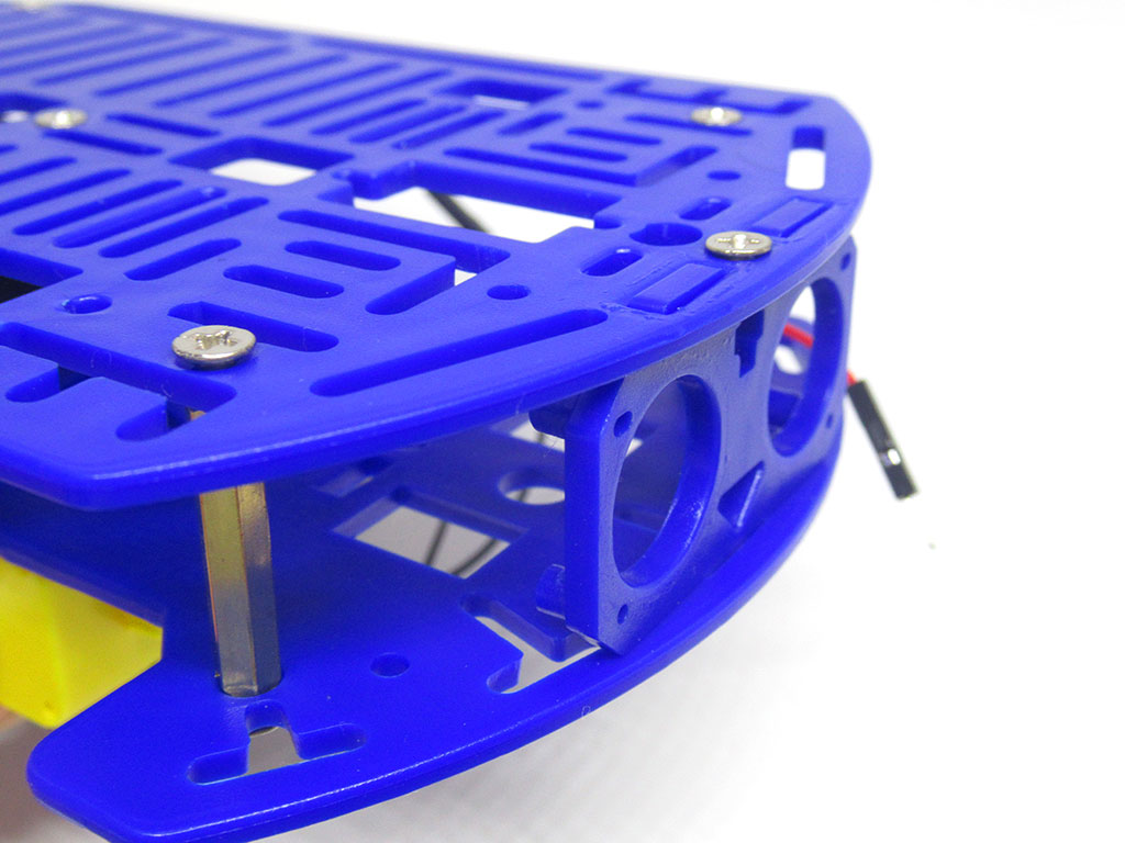
Next, attach the four motor holders onto the chassis.
Attach the IR sensor holder into the chassis as shown.
Align the holes on the motor to those found on the motor holder.
Insert an M3*30 screw into the holes as shown.
Do the same for the other motor and motor holder.
Attach nuts and screw them onto both M3*30 screws.
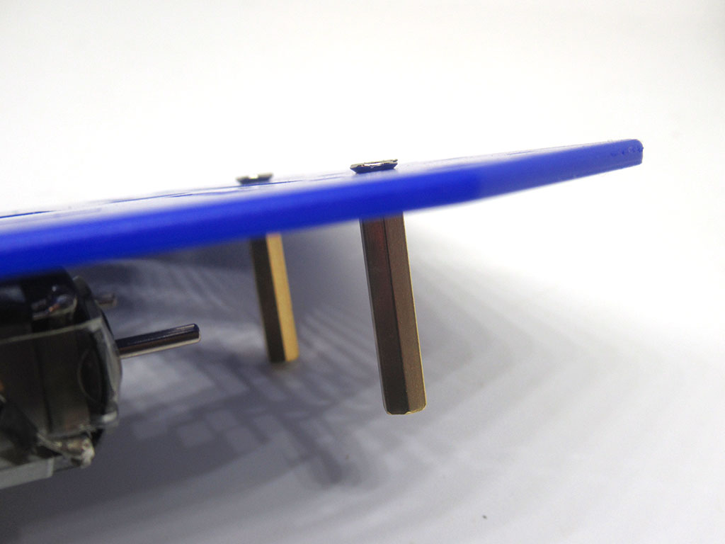
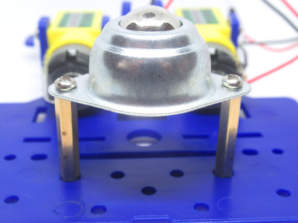
First, attach two of the L25 spacers to the chassis with M3*6 flathead screws.
Then align the omni wheel against the spacers so their holes are aligned.
Insert two more M3*6 flathead screws to attach the omni wheel to the spacers.
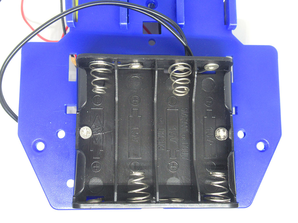
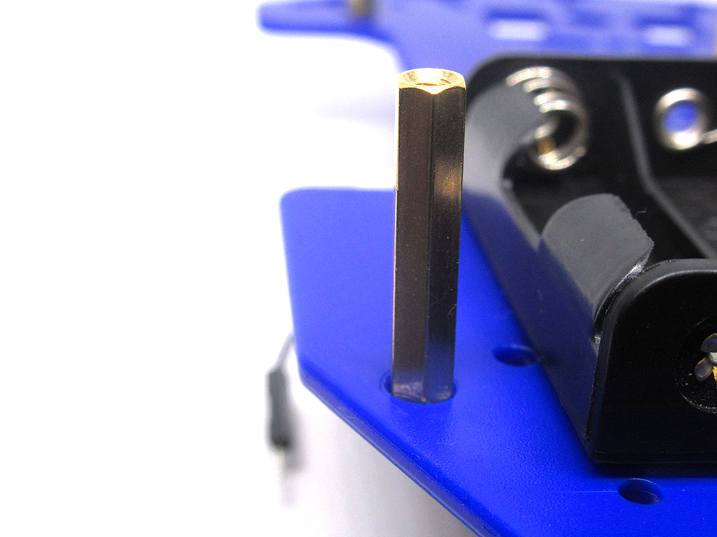
To connect the battery enclosure to the chassis, use two M3*10 flathead screws and M3 nuts.
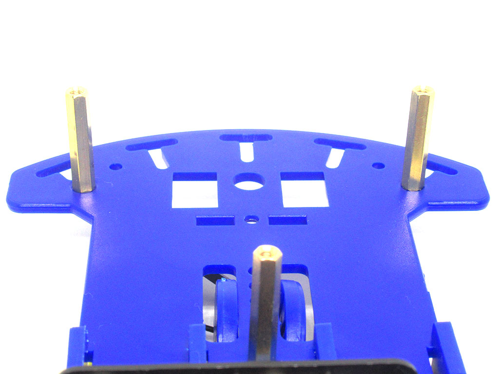
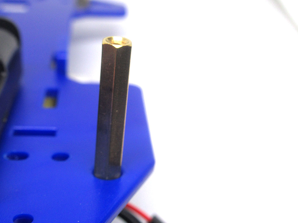
To put the top and bottom chassis parts together, we will first need to attach five of the L25 spacers to the bottom chassis with M3*6 flathead screws.

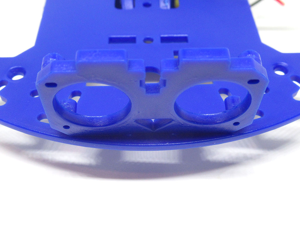
Now attach the ultrasonic module holder to the front of the bottom chassis.
Step 9 Attach top chassis plate to bottom chassis plate with nuts and flat head screws (M3*10 and M3*6)
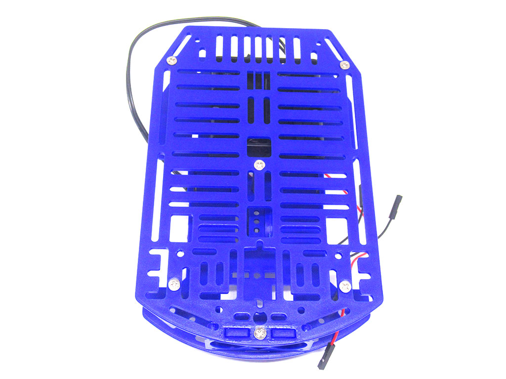
Next, align the top chassis to the bottom chassis so that the holes on each plate meet.
Attach the top chassis plate to the bottom chassis plate with M3*6 flathead screws.
Attach the top chassis plate to the ultrasonic module holder with an M3*10 flathead screw.

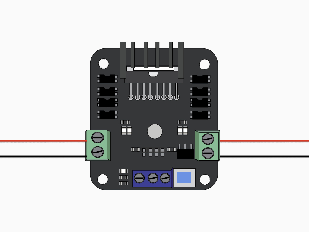
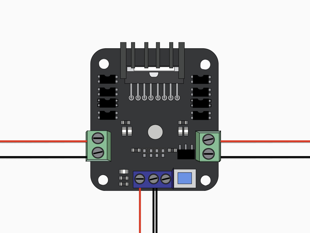
The motor driver controller is designed for use with simple DC motors as the ones found in the kit.
Now connect the motors to the motor controller as shown.
Make sure the red and black wires from one motor is attached to OUT1 and the pair from the other motor is attached to OUT2.

Insert the red jumper wire from the battery enclosure into VIN on the motor controller board.
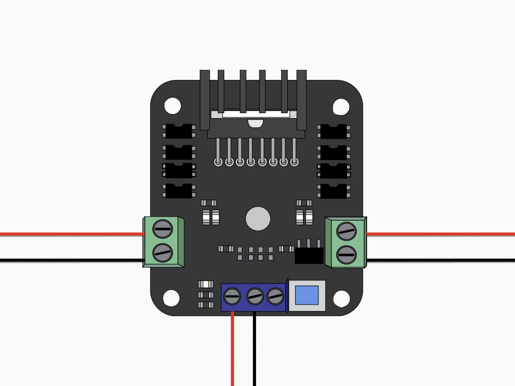
Next, insert the black jumper wire of the battery enclosure into the motor screw terminal labelled GND.
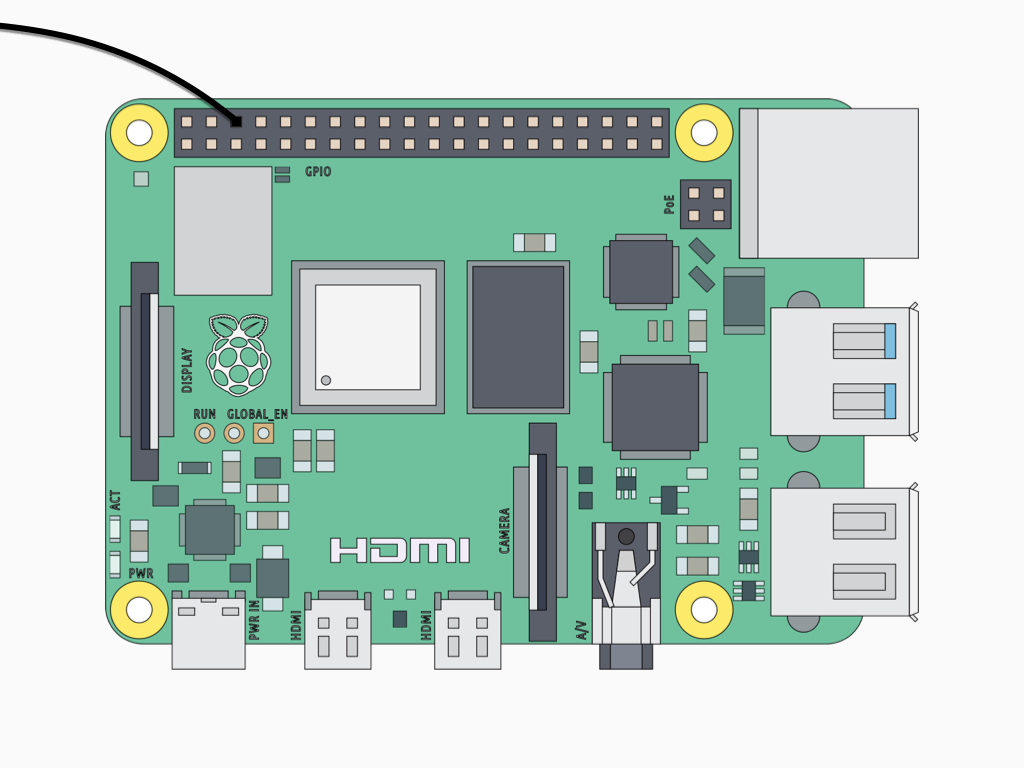
Next, connect the other end of the M-F black jumper wire from GND on the motor controller board to a GND pin on the Raspberry Pi.
Insert a black jumper wire into the motor screw terminal labelled GND.


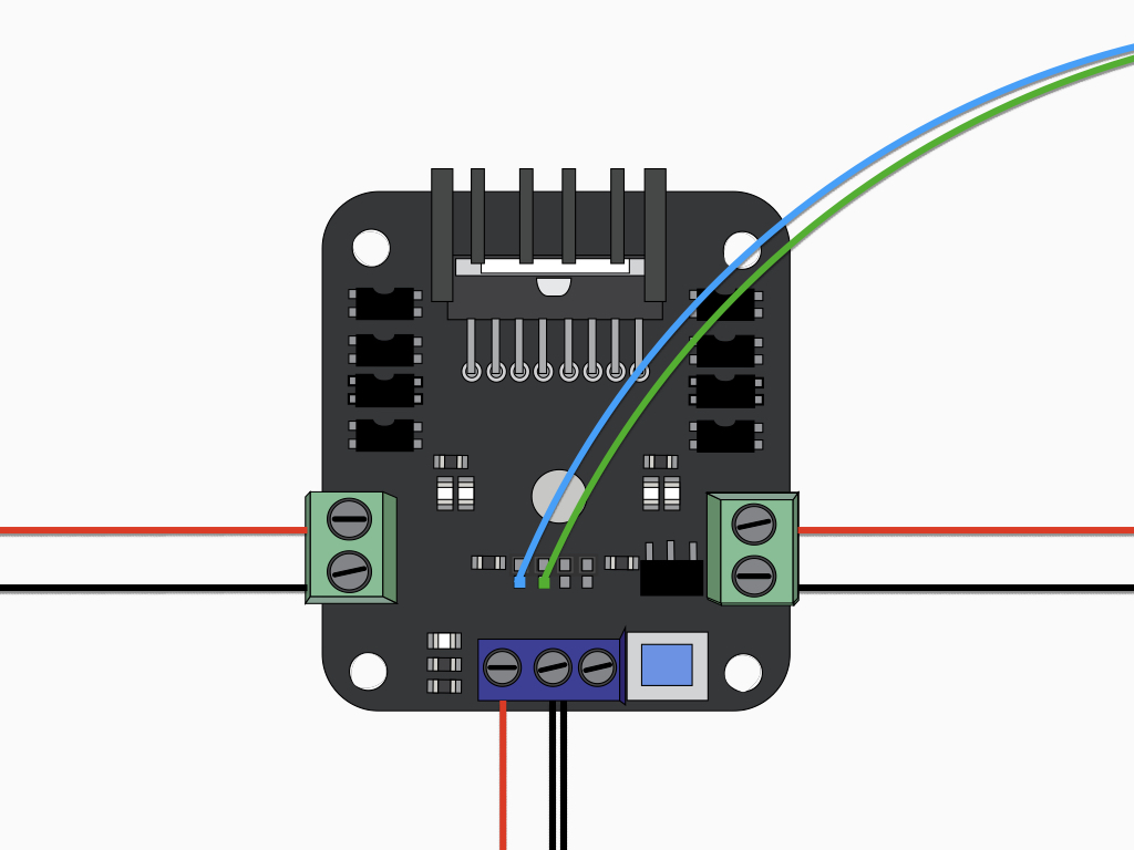

Connect a F-M jumper wire from IN2 pin on the motor controller board to GPIO27 on the Raspberry Pi 4.


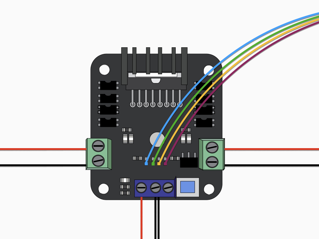
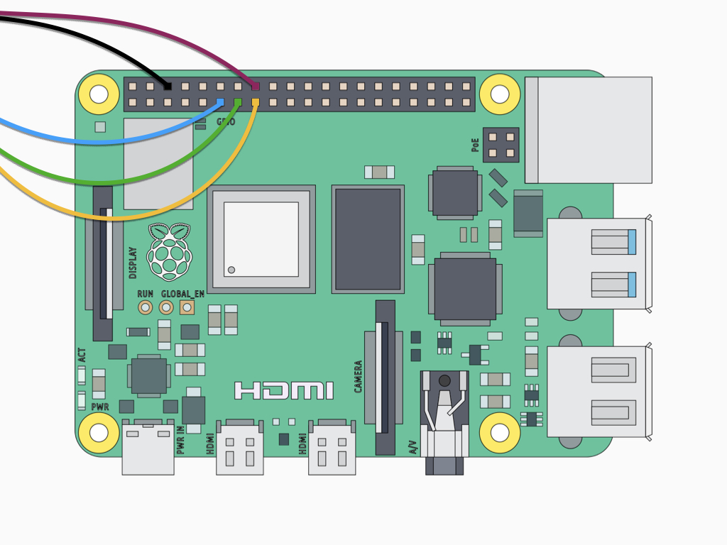
Connect a F-M jumper wire from IN4 to GPIO23 on the Raspberry Pi 4.
You may notice that there is a row of four unused pins above the IN1 to IN4 pins. These include the ENA and ENB pins. Leaving them jumpered will let it derive 5V from the motor supply, enabling the motors. In this guide, we will leave these pins jumpered. Alternatively, you can try to use the ENA and ENB pins to control motor speed using pulse width modulation (PWM).
Make sure a micro SD card with Raspbian Buster is inserted into the micro SD card slot on the Raspberry Pi 4.
Then connect the powerbank to the 5V USB-C power connector, use a USB (F) to USB-C (M) adapter if required.
from gpiozero import Robot
from time import sleep

robot = Robot(left = (27, 17), right = (22, 23))
while True:
  robot.forward()
  sleep(1)
  robot.stop()
You might wonder what the difference is between sleep() and robot.stop(). Essentially as its name suggests, the sleep() function from Python's time module pauses your Python program. On the other hand, robot.stop() does not pause the entire program.
With the Raspberry Pi 4 booted up, open up the Thonny IDE or use the nano editor to write the first program for the robot to move forwards.
Start by importing the required libraries, gpiozero and time.
Next, create a Robot object. This object is a 2-tuple containing the robot's left and right motor values.
Make the robot move forward with the robot.forward
Next, get it to pause for 1 second with the sleep function
from gpiozero import Robot
from time import sleep

robot = Robot(left = (27, 17), right = (22, 23))
while True:
  robot.forward()
  sleep(1)
  robot.backward()
  sleep(1)
  robot.right()
  sleep(1)
  robot.left()
  sleep(1)
There are five commands you can use to move the robot using gpiozero. These can be combined to make the robot move in different ways:
robot.forward()
robot.backward()
robot.right()
robot.left()
robot.stop()
robot.backward()
robot.right()
robot.left()
robot.stop()
Save and run the program in Thonny IDE or by entering the following command in the terminal: python yourprogramname.py
For more guides, check out https://www.littlebird.com.au/a/how-to/#raspberrypi to learn even more. Happy hacking!
We're done with our two-wheeled pre-programmed Raspberry Pi robot. In the next guide, learn how to incorporate an ultrasonic distance sensor into the robot and get it to avoid obstacles.