Pulse Monitor with EagLED
Create a BPM monitor with EagLED
Written By: Cherie Tan
Difficulty
Medium
Steps
25
The Pulse Sensor is a plug-and-play, heart-rate sensor for Arduino and Arduino-compatible microcontrollers such as the EagLED, which has an ATMega32U4. This pulse sensor adds amplification and noise cancellation circuitry, and will enable you to get reliable pulse readings.
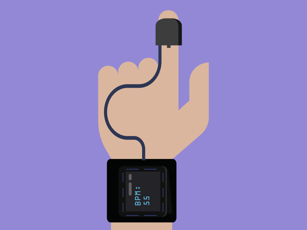
In this guide, we'll prototype a simple heart rate monitor with the pulse sensor, alligator clips and EagLED, then it will be moved onto felt fabric.
Complete this guide to create your own heart rate monitor with EagLED.
This project uses the EagLED board along with a Pulse Sensor Amped to create a wearable pulse monitor that will measure heart beats per minute (BPM).
BPM is a measure of an average of some beats over time. Yup, your heart doesn't actually beat with the regularity of clockwork. In actuality, it speeds up and slows down as your activities vary throughout the day.
Generally, a low BPM indicates rest, while a high BPM corresponds with exertion or even anxiety. Many things can affect your heart rate, including: physical activity, fitness level, air temperature, emotions, medication, and age.
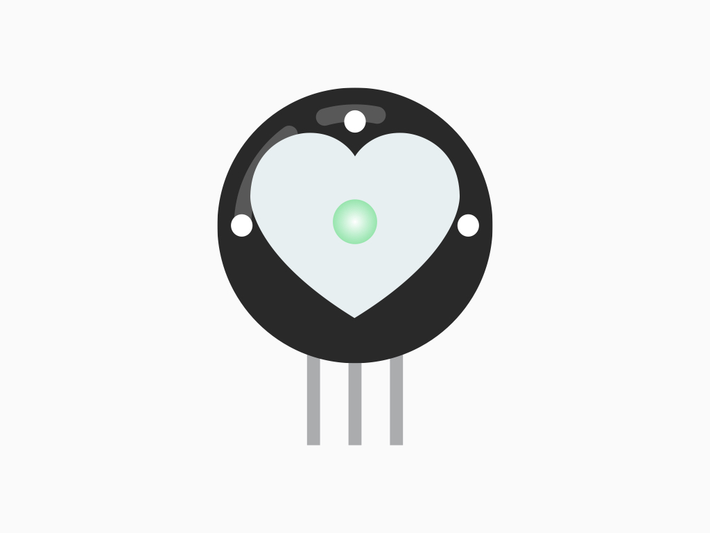
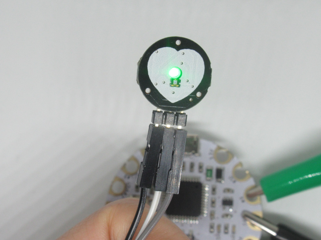
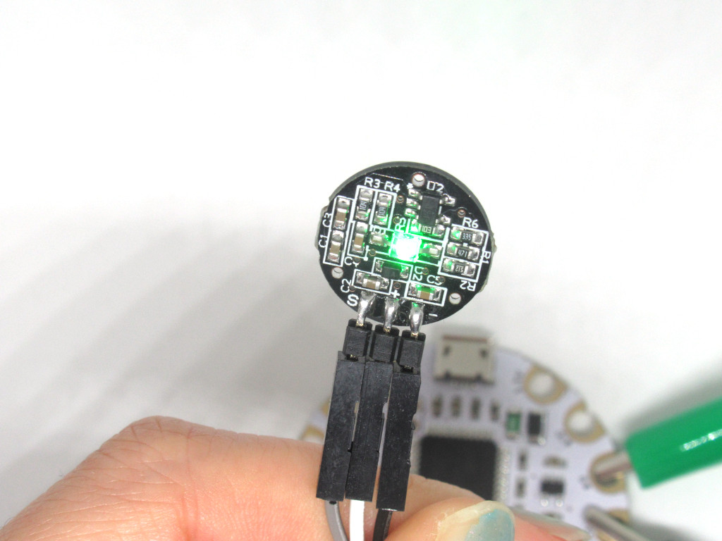
The Pulse Sensor Amped works by using photoplethysmography (PPG), which measures differences in light absorption. This is a technique used for non-invasive heart rate monitoring.
On one side of the sensor, there is a green LED. On the other side, there is a light-sensitive diode.
When placed on say your finger or earlobe, this green light penetrates the skin! Some of this green light is then reflected back to the sensor, and measured by the light-sensitive diode.
When blood pulses through your veins, more green light absorbed.
In between beats, there is less green light absorbed due to the absence of blood.
When blood pulses through your veins, more green light absorbed.
In between beats, there is less green light absorbed due to the absence of blood.
The heart pulse signal that comes out of a photoplethysmograph is an analog signal reflecting fluctuations in voltage:
If the amount of light incident on the sensor remains constant, then the signal value will remain close to 512.
More light and the signal goes up, less light and the signal goes down.
If the amount of light incident on the sensor remains constant, then the signal value will remain close to 512.
More light and the signal goes up, less light and the signal goes down.
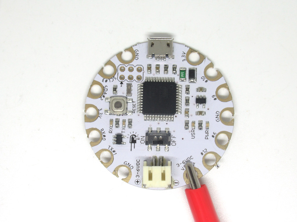
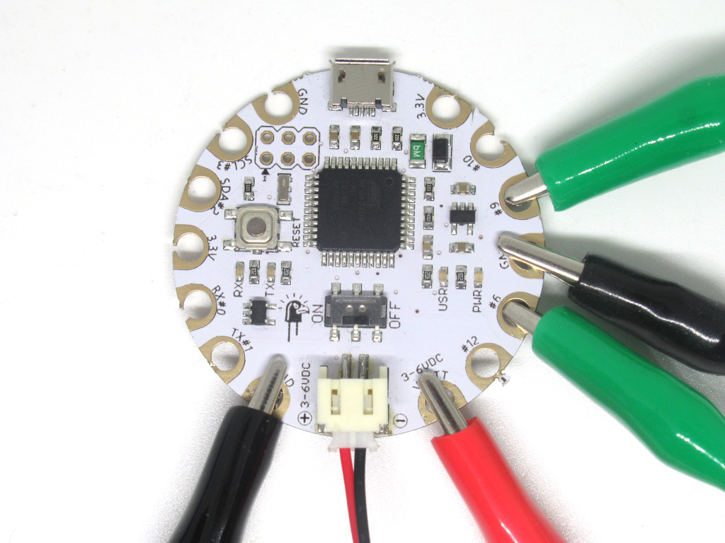
To begin prototyping with alligator clips, first connect a red alligator clip to '+' on Pulse Sensor.
Next, connect the other end of the alligator clip to 'VBATT' on EagLED
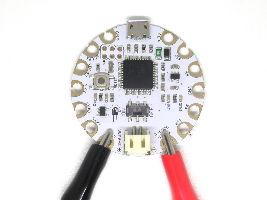
Next, connect a black alligator clip to '-' on Pulse Sensor
Connect the other end of this alligator clip to 'GND' on EagLED
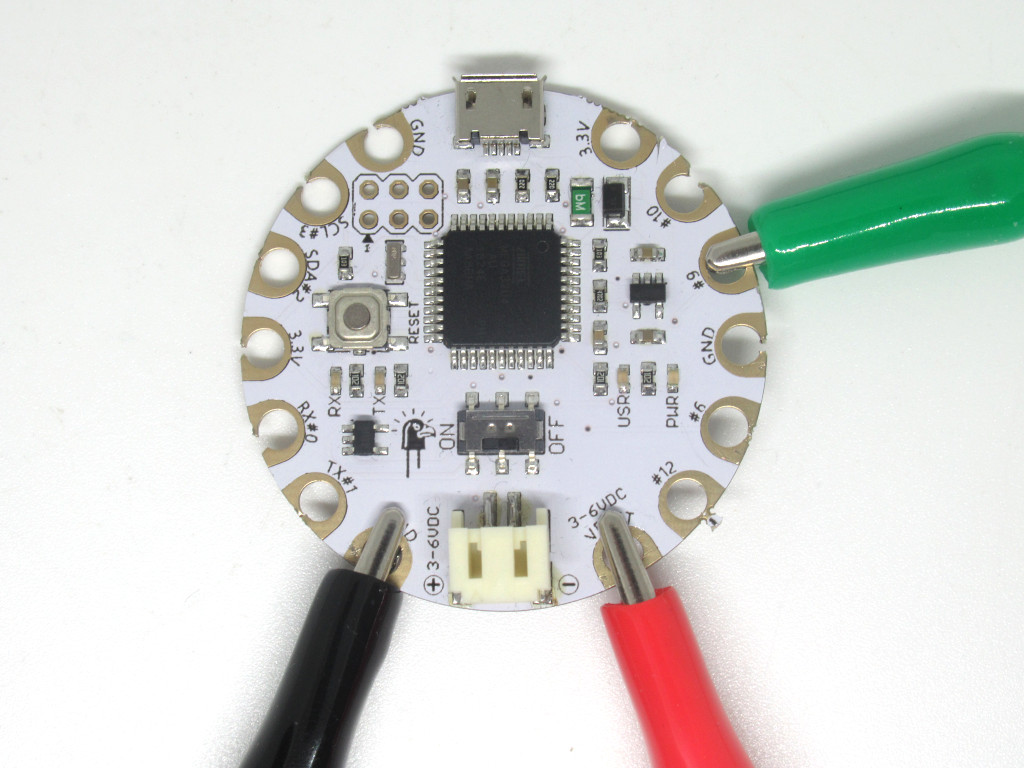
Next, connect another alligator clip to 'S' on Pulse Sensor
Connect the other end to '#A9' on EagLED
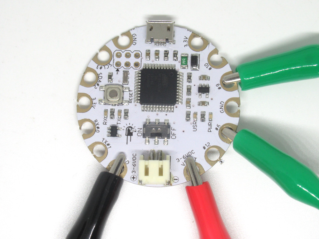
Get out a heart-shaped LED and connect another alligator clip to '+' on LED
Next, connect the other end to '#6' on EagLED
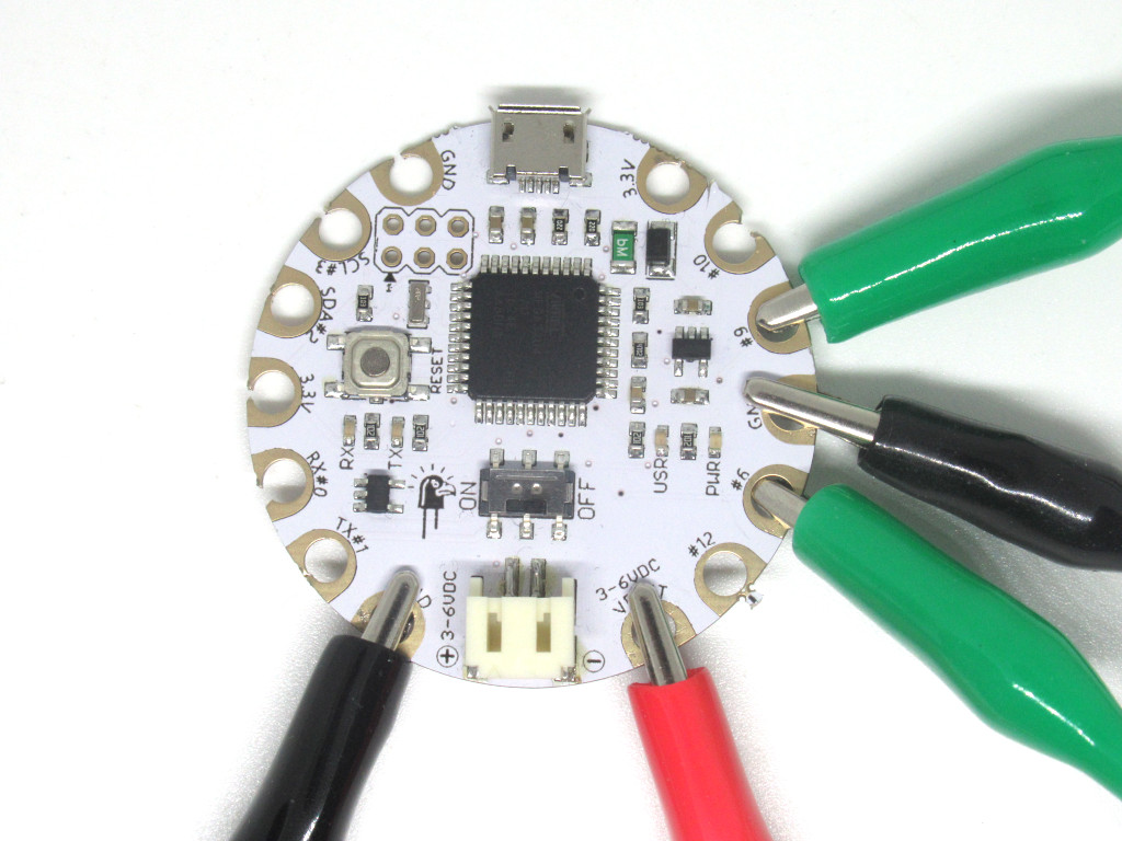
Connect another black alligator clip to '-' on LED
Connect the other end of the alligator clip to 'GND' on EagLED
The EagLED can be powered by a USB cable or a LiPo battery. In this guide, we'll connet it to a LiPo battery.
Connect the 180mAh LiPo battery to the JST connector found on the EagLED.
Scroll down to find 'PulseSensor Playground'
Click on the 'Install' button
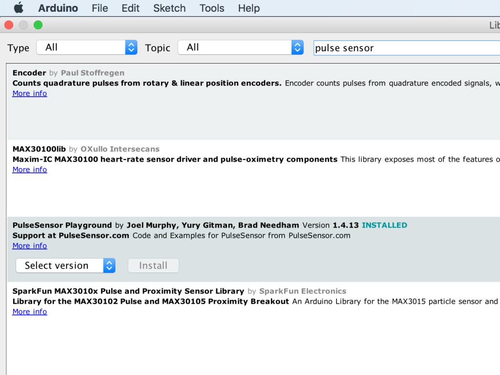
Type 'pulse sensor' in the search field
Before we can program the pulse sensor, the Pulse Sensor library will need to be installed. Go to Tools > Manage Libraries ...
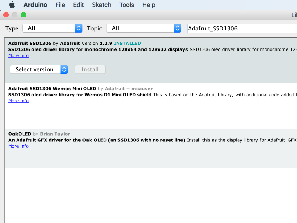
You will also need a library for the SSD1306 OLED screen. Type 'pulse sensor' in the search field.
Find 'Adafruit_SSD1306'
Click on the 'Install' button
/*  Getting_BPM_to_Monitor prints the BPM to the Serial Monitor, using the least lines of code and PulseSensor Library.
 *  Tutorial Webpage: https://pulsesensor.com/pages/getting-advanced
 *
--------Use This Sketch To------------------------------------------
1) Displays user's live and changing BPM, Beats Per Minute, in Arduino's native Serial Monitor.
2) Print: "♥  A HeartBeat Happened !" when a beat is detected, live.
2) Learn about using a PulseSensor Library "Object".
4) Blinks LED on PIN 6 with user's Heartbeat.
--------------------------------------------------------------------*/

#define USE_ARDUINO_INTERRUPTS true    // Set-up low-level interrupts for most acurate BPM math.
#include <PulseSensorPlayground.h>     // Includes the PulseSensorPlayground Library.

//  Variables
const int PulseWire = A9;       // PulseSensor PURPLE WIRE connected to ANALOG PIN 0
const int LED = 6;          // The on-board Arduino LED, close to PIN 13.
int Threshold = 550;           // Determine which Signal to "count as a beat" and which to ignore.
                               // Use the "Gettting Started Project" to fine-tune Threshold Value beyond default setting.
                               // Otherwise leave the default "550" value.

PulseSensorPlayground pulseSensor;  // Creates an instance of the PulseSensorPlayground object called "pulseSensor"


void setup() {

  Serial.begin(9600);          // For Serial Monitor

  // Configure the PulseSensor object, by assigning our variables to it.
  pulseSensor.analogInput(PulseWire);
  pulseSensor.blinkOnPulse(LED);       //auto-magically blink Arduino's LED with heartbeat.
  pulseSensor.setThreshold(Threshold);

  // Double-check the "pulseSensor" object was created and "began" seeing a signal.
   if (pulseSensor.begin()) {
    Serial.println("We created a pulseSensor Object !");  //This prints one time at Arduino power-up,  or on Arduino reset.
  }
}


void loop() {

 int myBPM = pulseSensor.getBeatsPerMinute();  // Calls function on our pulseSensor object that returns BPM as an "int".
                                               // "myBPM" hold this BPM value now.

if (pulseSensor.sawStartOfBeat()) {            // Constantly test to see if "a beat happened".
 Serial.println("♥  A HeartBeat Happened ! "); // If test is "true", print a message "a heartbeat happened".
 Serial.print("BPM: ");                        // Print phrase "BPM: "
 Serial.println(myBPM);                        // Print the value inside of myBPM.
}

  delay(20);                    // considered best practice in a simple sketch.

}
Connect the EagLED to the computer via USB cable
Upload this code to the EagLED
Then go to Tools > Serial Monitor
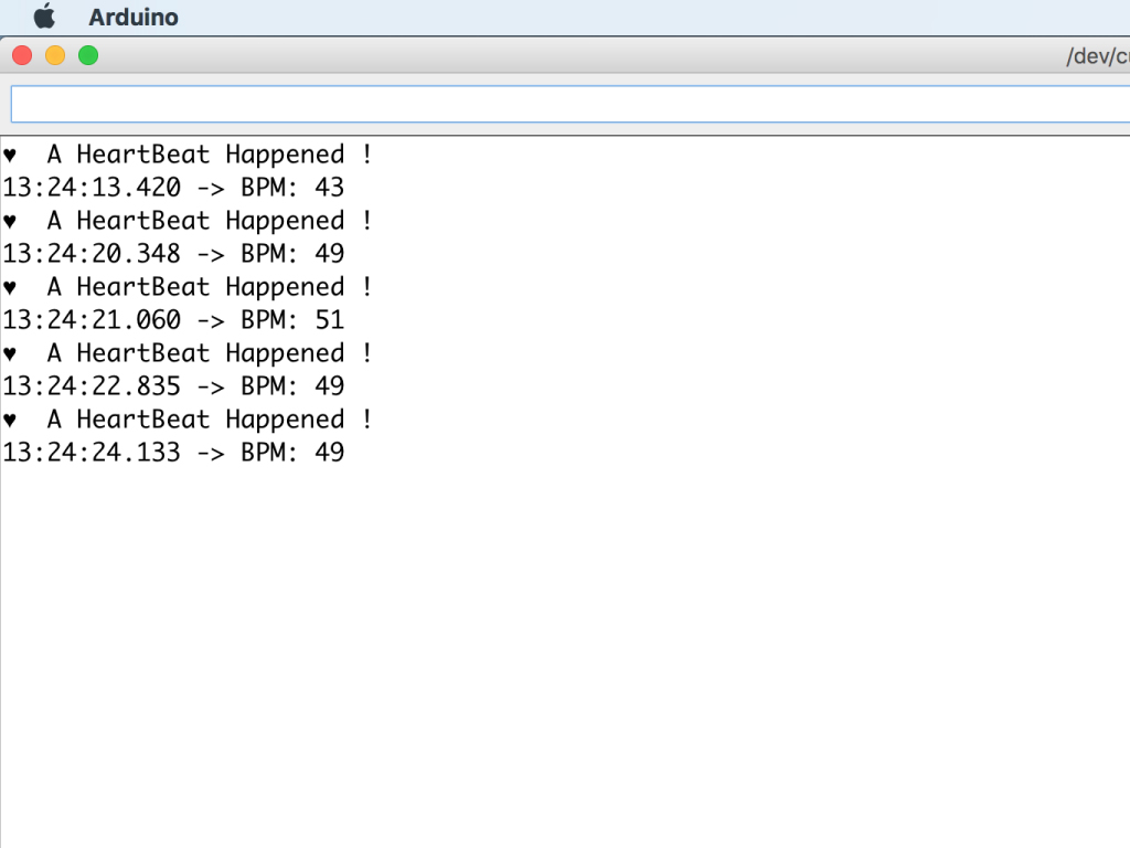
Place the pulse sensor against your finger or ear lobe, and you should see BPM readings soon enough.
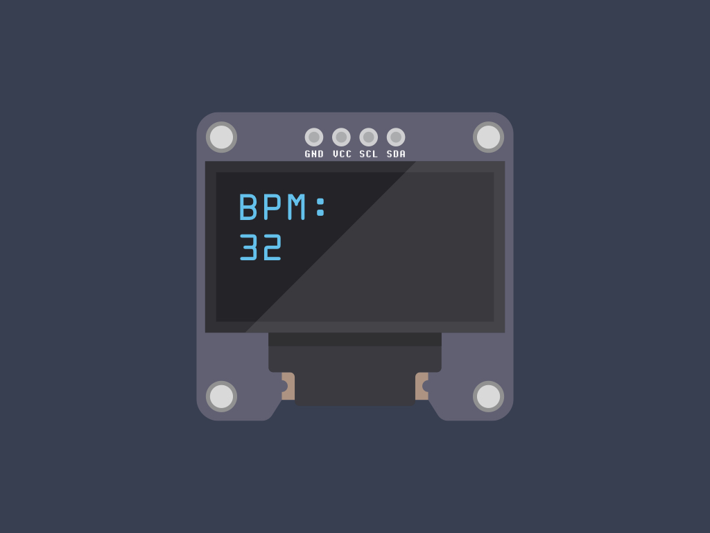
Next, instead of displaying the sensor readings to the Serial Monitor, we'll now get it to display on an OLED screen, specifically the SSD1306. We'll also omit the heart-shaped LED in the final build.
An OLED screen stands for organic light-emitting diode screen, composed of layers including layers of organic compound that lights up when fed with electricity.
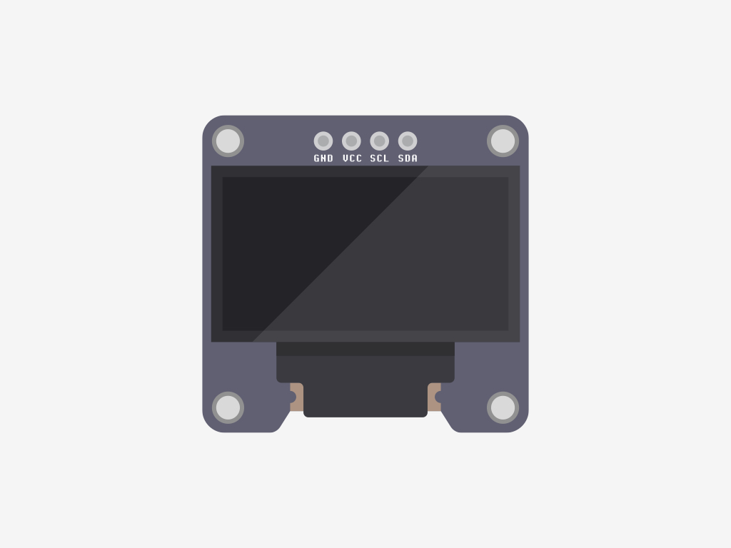
The SSD1306 OLED screen has four pins:
GND: In electronics, we define a point in a circuit to be a kind of zero volts or 0V reference point, on which to base all other voltage measurements. This point is called common ground or GND.
GND: In electronics, we define a point in a circuit to be a kind of zero volts or 0V reference point, on which to base all other voltage measurements. This point is called common ground or GND.
Voltage is the difference in electric potential between two points. As it is difficult to talk about voltage without a reference point, we need another point to compare it to.
VCC : While 'VCC' stands for Voltage Common Collector, we'll connect the VCC pin to 3.3V on the EagLED
Serial Clock (SCL)
Serial Data (SDA)
To connect the SCL and SDA pins to the EagLED, they must be connected to Pins 3 and 2.
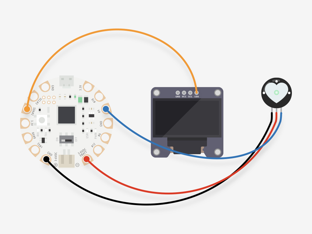
Attach an alligator clip from 'SDA#2' on the EagLED to 'SDA' on the OLED screen
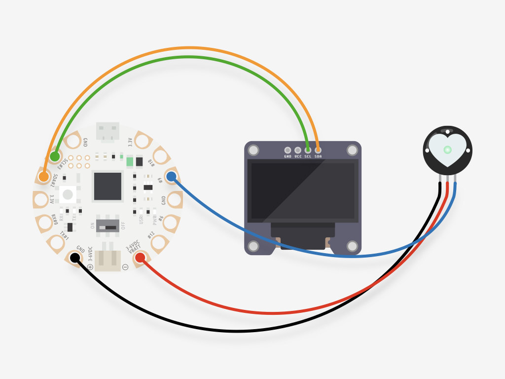
Attach an alligator clip from 'SCL#3' on the EagLED to 'SCL' on the OLED screen
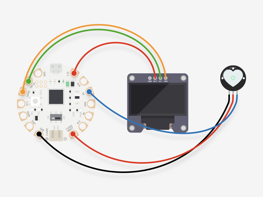
Attach an alligator clip from '3.3V' on the EagLED to 'VCC' on the OLED screen
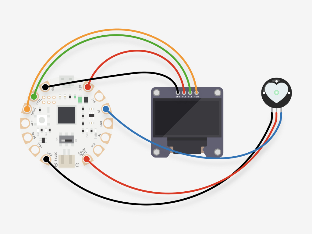
Attach an alligator clip from 'GND' on the EagLED to 'GND' on the OLED screen
#define USE_ARDUINO_INTERRUPTS true    // Set-up low-level interrupts for most acurate BPM math.
#include <PulseSensorPlayground.h>     // Includes the PulseSensorPlayground Library.
#include <Wire.h>
#include <Adafruit_SSD1306.h>

#define OLED_RESET 4
Adafruit_SSD1306 display(OLED_RESET);

//  Variables
const int PulseWire = A9;       // PulseSensor PURPLE WIRE connected to ANALOG PIN 0
int Threshold = 550;           // Determine which Signal to "count as a beat" and which to ignore.
// Use the "Gettting Started Project" to fine-tune Threshold Value beyond default setting.
// Otherwise leave the default "550" value.


PulseSensorPlayground pulseSensor;  // Creates an instance of the PulseSensorPlayground object called "pulseSensor"


void setup() {

  display.begin(SSD1306_SWITCHCAPVCC, 0x3C);  // initialize with the I2C addr 0x3D (for the 128x64)
  delay(2000);
  display.clearDisplay();   // clears the screen and buffer
  Serial.begin(9600);          // For Serial Monitor
  // Configure the PulseSensor object, by assigning our variables to it.
  pulseSensor.analogInput(PulseWire);
  pulseSensor.setThreshold(Threshold);

  // Double-check the "pulseSensor" object was created and "began" seeing a signal.
  if (pulseSensor.begin()) {
    Serial.println("We created a pulseSensor Object !");  //This prints one time at Arduino power-up,  or on Arduino reset.
  }
}


void loop() {

  int myBPM = pulseSensor.getBeatsPerMinute();  // Calls function on our pulseSensor object that returns BPM as an "int".
  // "myBPM" hold this BPM value now.

  if (pulseSensor.sawStartOfBeat()) {            // Constantly test to see if "a beat happened".
    display.clearDisplay();
    display.setTextSize(2);
    display.setTextColor(WHITE);
    display.setCursor(0, 0);
    display.println("BPM: ");
    display.println(myBPM);
    display.display();
  }

  delay(20);                    // considered best practice in a simple sketch.

}
Connect EagLED to the computer via microUSB cable
Make sure the EagLED switch is flicked to 'ON'
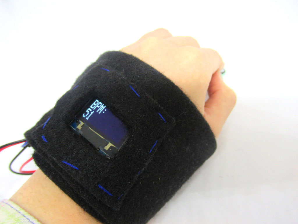
Upload the following sketch to the EagLED. The OLED screen should now display the BPM!
To move the prototype to a more permanent solution, remove the alligator clips and solder the OLED screen onto the EagLED:
'GND' to 'GND'
'GND' to 'GND'
'VCC' to '3.3V'
'SCL' to 'SCL#3' '
SDA' to 'SDA#2
Next, solder the Pulse Sensor pins to the EagLED: '-' to 'GND'
'+' TO 'VBATT'
'S' to '#A9'
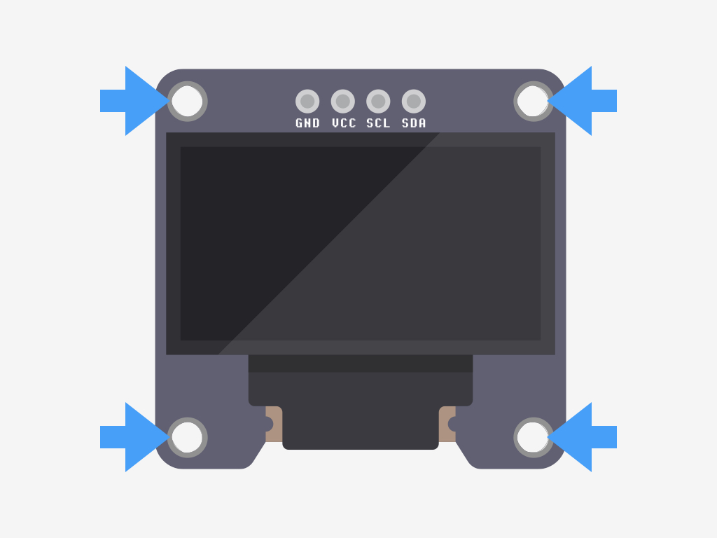
There are four mounting holes on the OLED module.
Use regular, non-conductive thread and sew the OLED screen in place.
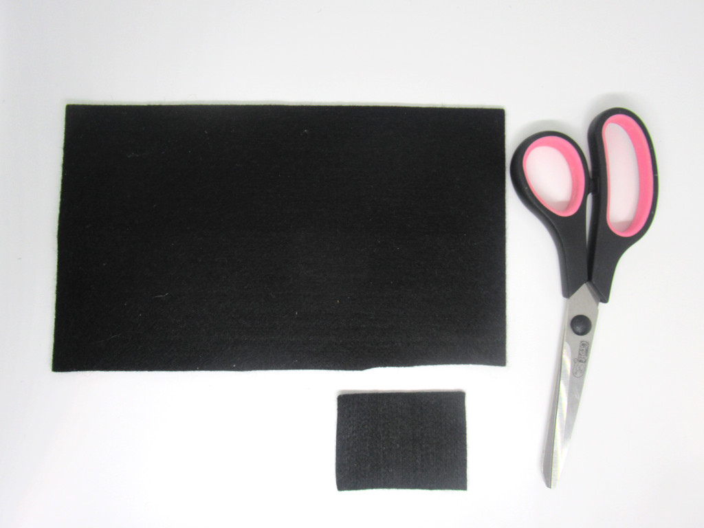
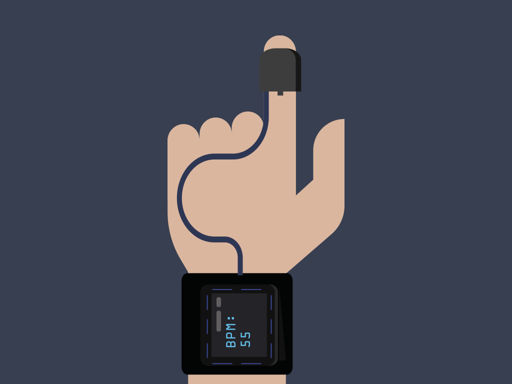
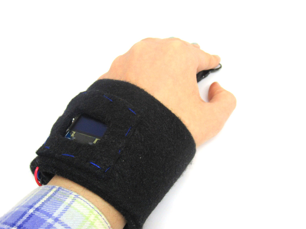
In this guide, we'll move the prototype onto felt fabric. Cut out a rectangular piece of felt fabric, making sure that the length of it will wrap around your wrist
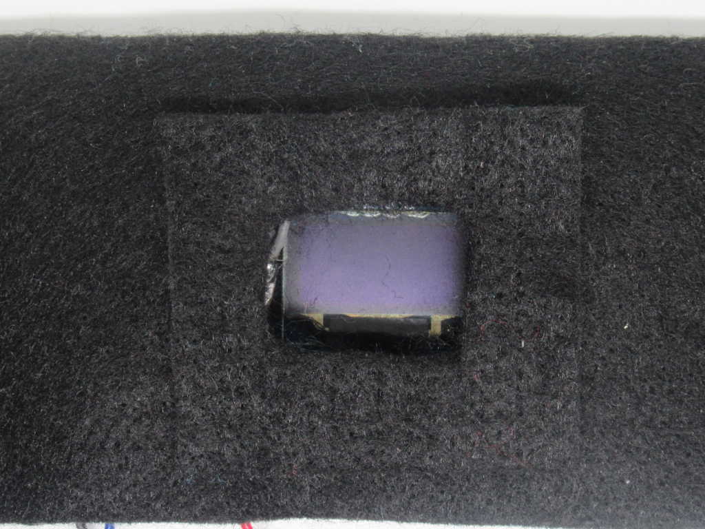
Cut out another rectangular shaped piece of felt fabric. This will be placed on top of the OLED screen.
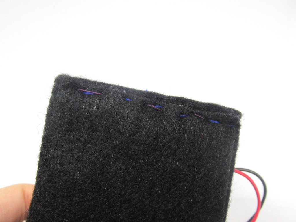
Finally, sew both ends of the felt fabric strap together.
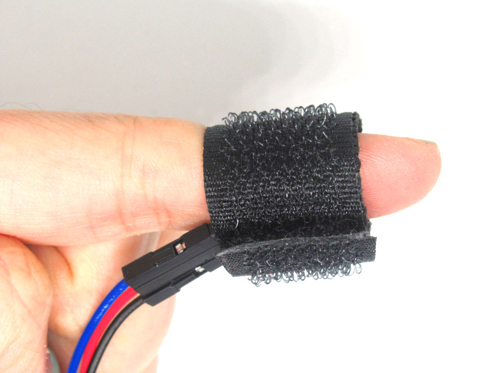
You may want to use a Velcro strap to attach the Pulse Sensor around your finger for accurate readings.
Some suggestions on how to go further:
You may also want to move the components onto a waterproof or more durable solution such as a 3D-printed strap.
Add an RGB LED ring to create a breath pacer device with the EagLED and Pulse Sensor Amped.
You may also want to move the components onto a waterproof or more durable solution such as a 3D-printed strap.
Add an RGB LED ring to create a breath pacer device with the EagLED and Pulse Sensor Amped.