Laser Head Sensor with micro:bit
Make a Tripwire Alarm with micro:bit
Written By: Cherie Tan
Difficulty
Easy
Steps
16
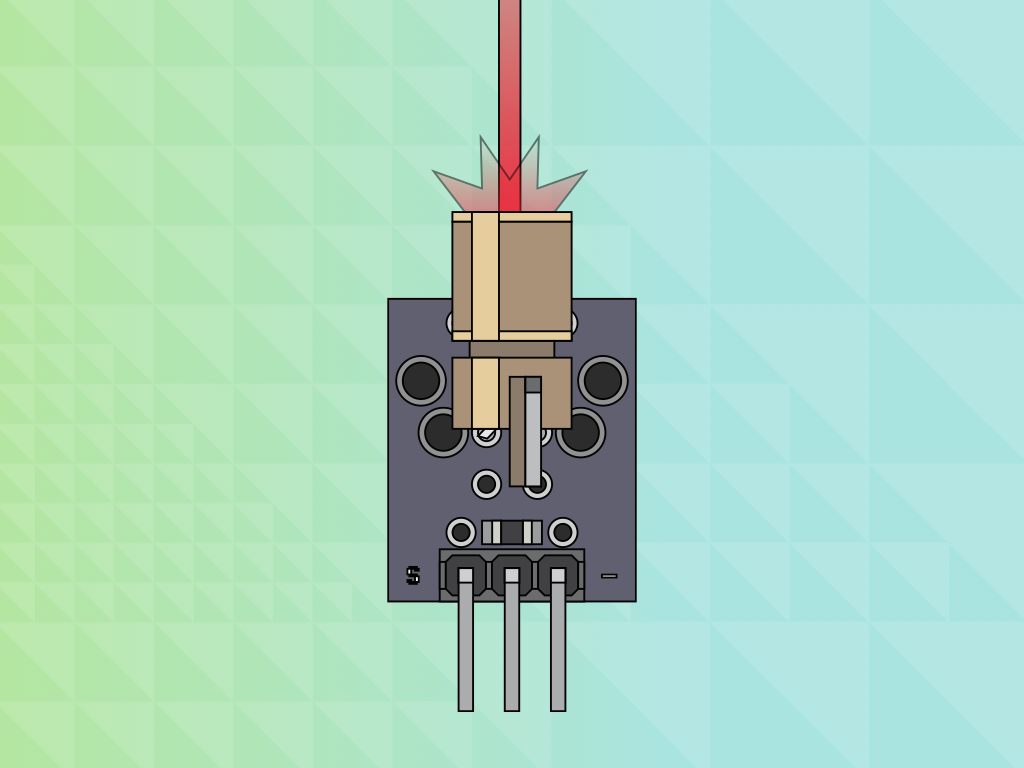
A laser head sensor module is one of many useful external components that you can connect to your micro:bit!
In this guide, you will learn to connect the micro:bit with a laser head sensor module and create your own tripwire alarm system. With the addition of a light dependent resistor, the alarm will start to sound when the laser is broken.
By finishing this guide, you will have created a simple tripwire alarm system.
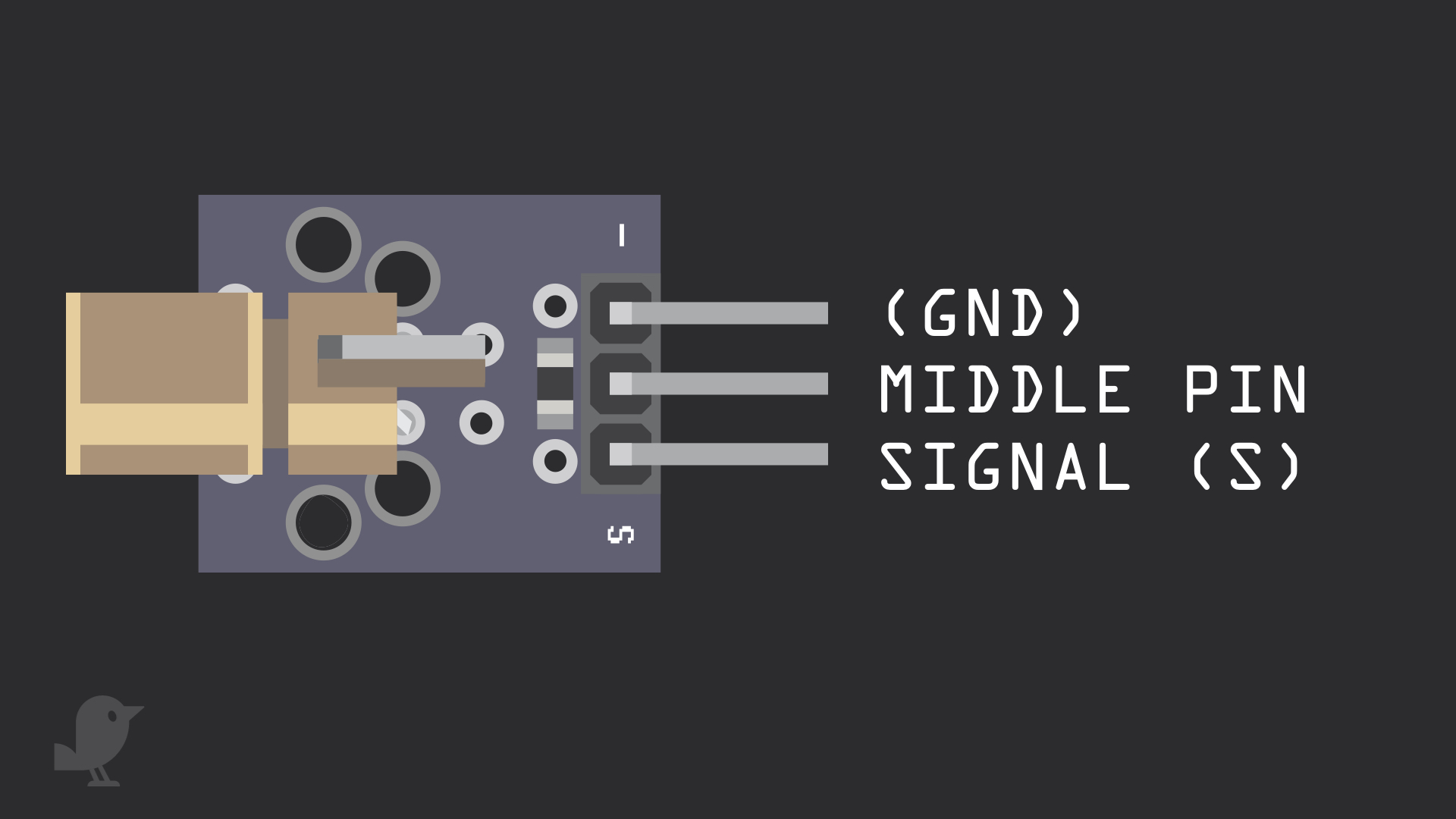
Let's take a closer look at the laser head sensor module. It has three pins:
GND: Though it is labelled '-' on the module, this is the the 'GND' pin. In electronics, we define a point in a circuit to be a kind of zero volts or 0V reference point, on which to base all other voltage measurements. This point is called ground or GND.
Middle Pin: No connection required here
Signal: This pin is the signal pin, which is the input to control the module
Voltage is the difference in electric potential between two points. As it is difficult to talk about voltage without a reference point, we need another point to compare it to.
input.onButtonPressed(Button.A, function () {
    pins.digitalWritePin(DigitalPin.P2, 0)
})
input.onButtonPressed(Button.B, function () {
    pins.digitalWritePin(DigitalPin.P2, 1)
})
Now that we have connected the laser head module to the micro:bit, we will program it! We will use the two push buttons on the micro-bit to turn the laser on and off. Open up MakeCode editor
Click on the 'Projects' button then click on 'New Project ...'
Add this code to the Javascript interface
Upload this code to the micro:bit and press button A and B to see what it does!
These are the two buttons found on the micro:bit.
let sensorVal = 0
input.onButtonPressed(Button.A, function () {
    pins.digitalWritePin(DigitalPin.P2, 1)
})
input.onButtonPressed(Button.B, function () {
    pins.digitalWritePin(DigitalPin.P2, 0)
})
basic.forever(function () {
    sensorVal = pins.analogReadPin(AnalogPin.P1)
    if (sensorVal > 600) {
        basic.showNumber(sensorVal)
        music.playTone(262, music.beat(BeatFraction.Double))
    } else {
        basic.showNumber(sensorVal)
    }
})
We have also added a light dependent resistor module and a buzzer module to the circuit. Let's learn to use them now. Upload this code to the Javascript interface.
Pin 2 has been used to connect to signal (S) of the laser head module, while pin 0 is connected to input or output signal (I/O) of the buzzer module.
If sensorVal is more than 600, the micro:bit will display the value and then sound the alarm by playing a Middle C tone for 2 beats each time.
Else, the micro:bit will display the sensorVal when the laser is not broken.
let sensorVal = 0
input.onButtonPressed(Button.A, function () {
    pins.digitalWritePin(DigitalPin.P2, 1)
})
input.onButtonPressed(Button.B, function () {
    pins.digitalWritePin(DigitalPin.P2, 0)
})
basic.forever(function () {
    sensorVal = pins.analogReadPin(AnalogPin.P1)
    if (sensorVal > 600) {
        music.playTone(262, music.beat(BeatFraction.Double))
        basic.showIcon(IconNames.Angry)
    } else {
        basic.showIcon(IconNames.Happy)
    }
})
Let's change the code to add more visuals. Add this code to the Javascript interface.
When the trip wire alarm system goes off now, it will display an angry face using the micro:bit's LEDs. Otherwise, if all is well, it will display a smiley face on the LEDs.
let sensorVal = 0
input.onButtonPressed(Button.A, function () {
    pins.digitalWritePin(DigitalPin.P2, 1)
})
input.onButtonPressed(Button.B, function () {
    pins.digitalWritePin(DigitalPin.P2, 0)
})
radio.onReceivedString(function (receivedString) {
    basic.showString(receivedString)
})
basic.forever(function () {
    sensorVal = pins.analogReadPin(AnalogPin.P1)
    if (sensorVal > 600) {
        music.playTone(262, music.beat(BeatFraction.Double))
        basic.showIcon(IconNames.Angry)
        radio.sendString("\"Intruder alert!\"")
    } else {
        basic.showIcon(IconNames.Happy)
    }
})
If you have another micro:bit laying around, use the following MakeCode, else skip to the next step! Here, we will use another micro:bit to receive a message when the trip wire alarm system goes off. Add this code to the Javascript interface.
Now when the laser is broken and the sensorVal goes above 600, the second micro:bit will display the string, "Intruder alert!". This is done using "radio send string" and "on radio received". The two micro:bits can communicate with one another via radio.
It's time to upload the code to the micro:bit! Connect the micro:bit to your computer by using a microUSB cable
In MakeCode editor, click on the Download button
Find the hex file in your Downloads folder or where you have saved it to
Open up Finder on the MacOS or Explorer on Windows, and drag the hex file into MICROBIT under 'Devices' on the macOS. The micro:bit will flash for a few seconds and the trip wire alarm will be all set.