L298 Dual H-Bridge Motor Driver with micro:bit
Control the speed and rotation direction of two DC motors with the L298 and a micro:bit
Written By: Cherie Tan
Difficulty
Medium
Steps
24
Electric motors can be seen used in robotic hands, drones, 3D printers, and many modern devices.
In this guide, we'll show you how to get started with using the L298 H-Bridge Motor Driver with the micro:bit. This will allow speed and direction control of two DC motors at the same time. We'll program it to do so by using the MakeCode editor.
Complete this guide to learn the basics in getting DC motors to rotate forwards, backwards, and halting its movement.
There are many components that can be used in a circuit, but none are as versatile or as exciting as an electric motor!
The use of electric motors have made it possible for robotic hands to clutch, and for drones to fly in the air. Another example can be seen in 3D printers, which use specialised motor control circuits.
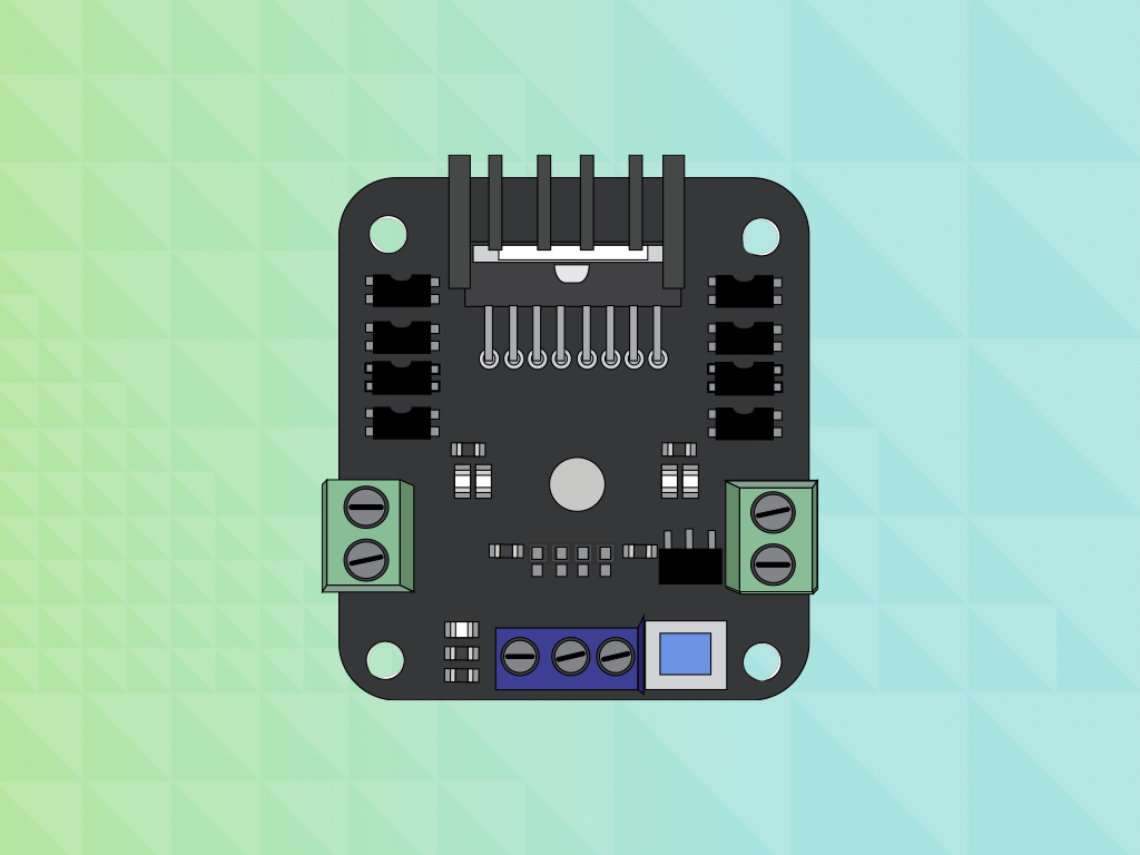
An easy way to control motors is with the use of a motor controller also known as a motor driver.
The module used in this guide is based on the L298 Dual H-Bridge Motor Driver Integrated Circuit.
The module used in this guide is based on the L298 Dual H-Bridge Motor Driver Integrated Circuit.
A H-bridge is a simple circuit that allows the control of a DC motor to go backward or forward. These circuits are constructed with transistors, specifically either with MOSFETs or bipolar transistors.
What are transistors? Think of them as basic building blocks of modern electronics. They are small electrical devices that can be found used in computers, clocks, calculators, and much more.
While you could build a H-bridge circuit from scratch, all this is already done for you with the L298 Dual H-Bridge Motor Driver Integrated Circuit.
In this guide, you'll learn how to connect this motor driver with a micro:bit, and program it to control two motors of up to 2A in both directions.
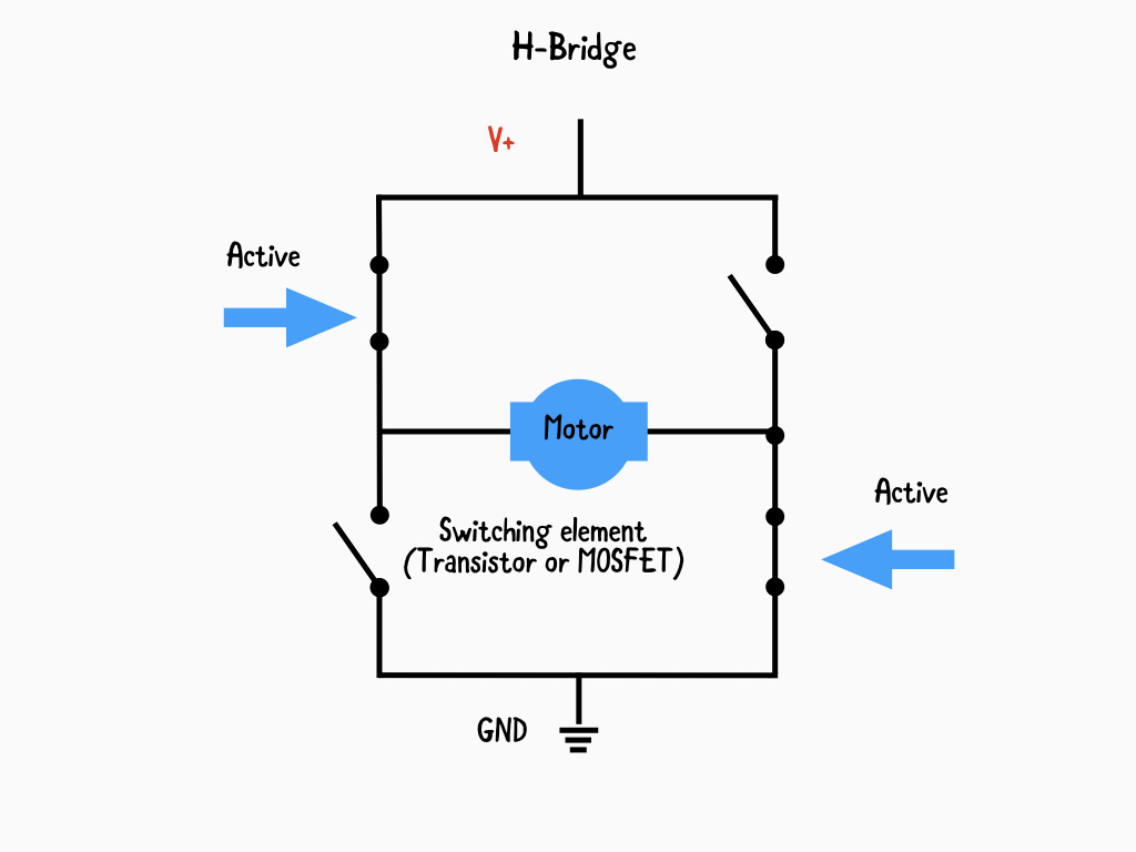
A H-Bridge circuit contains four switching elements i.e. transistors, MOSFETs, etc, with the motor at the center, forming a H-like configuration.
By activating two particular switches at the same time, the direction of current flow can be changed. This in turn changes the rotation direction of the motor.
So by using the H-Bridge Integrated Circuit included in the L298 H-Bridge Motor Driver, we can have complete control over the rotation direction of the DC motor. But, what about its speed?
While we could change the speed of a DC motor by changing its supply voltage, there are limitations to this.
1. Dropping a supplied voltage to 50% of the specified recommended voltage will cause the motor to cease to rotate
3. Applying a voltage that exceeds 30% of the recommended operating voltage may cause overheating and damage to the motor
1. Dropping a supplied voltage to 50% of the specified recommended voltage will cause the motor to cease to rotate
3. Applying a voltage that exceeds 30% of the recommended operating voltage may cause overheating and damage to the motor
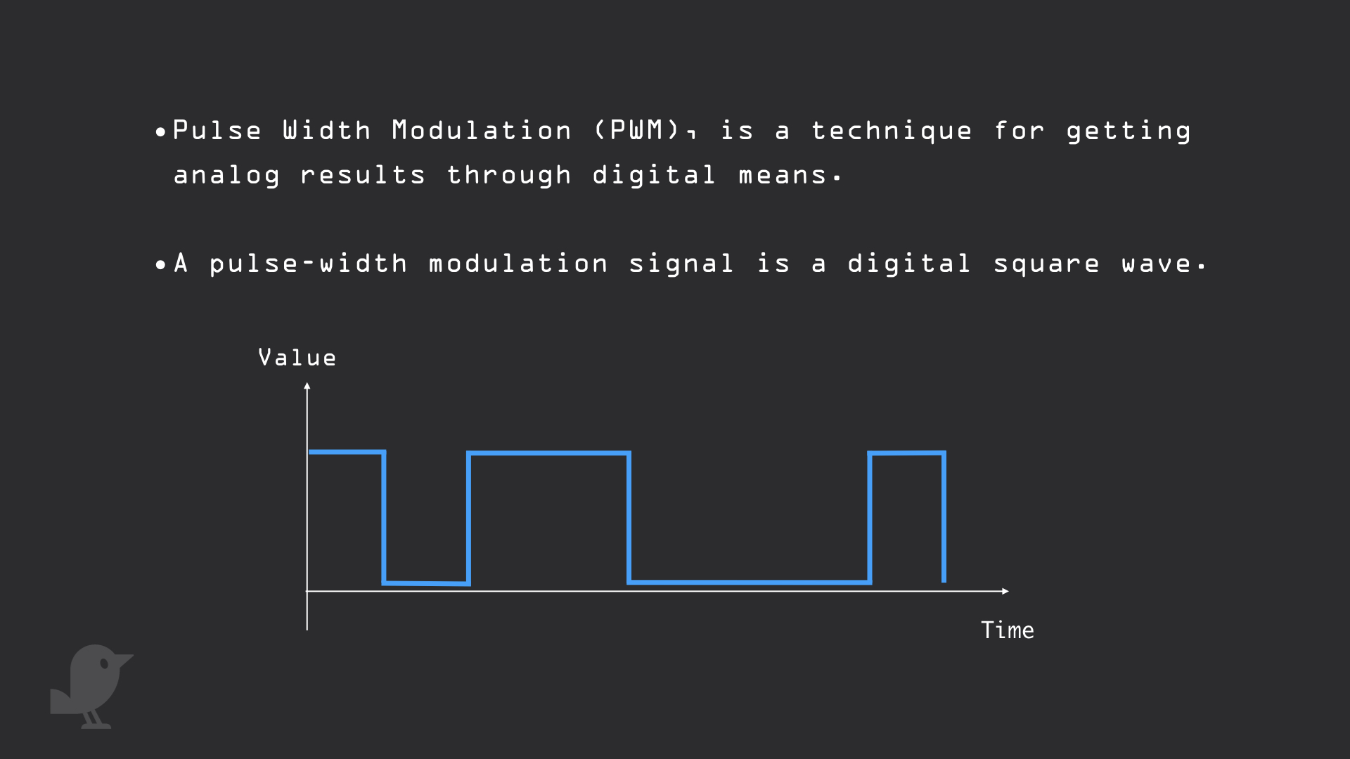
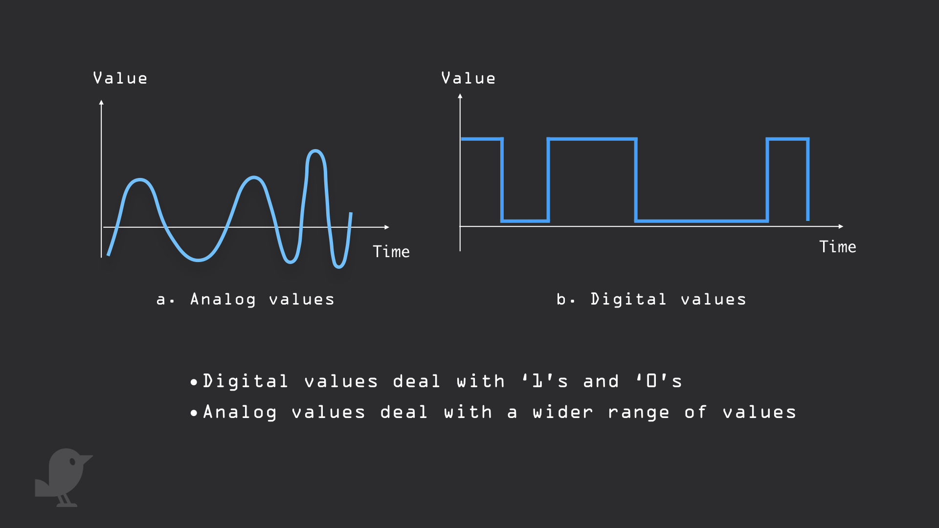
A more efficient method to control the speed of a DC motor is to use Pulse Width Modulation, or PWM for short.
What PWM does is it turns the motor rapidly ON and OFF. In this case, the PWM outputs from the micro:bit is connected to ENA and ENB input pins on the motor driver board. When these pins are HIGH, power is output to the motors; when these pins are LOW, there is no power to the motors. By turning power on and off very quickly, this adjusts the speed of the motor.
The longer the PWM duty cycle is, the faster the motor will rotate.
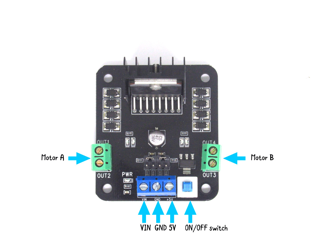
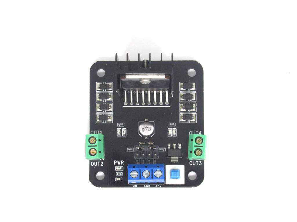
The pins on the L298 Dual H-Bridge Motor Drivers:
VIN - The VIN pin will be connected to the red wire of our 5V power supply
GND - This is the ground pin that we'll connect the black wire of our 5V power supply, and GND on the micro:bit.
5V - This is the 5V pin which we'll connect to 5V on the micro:bit
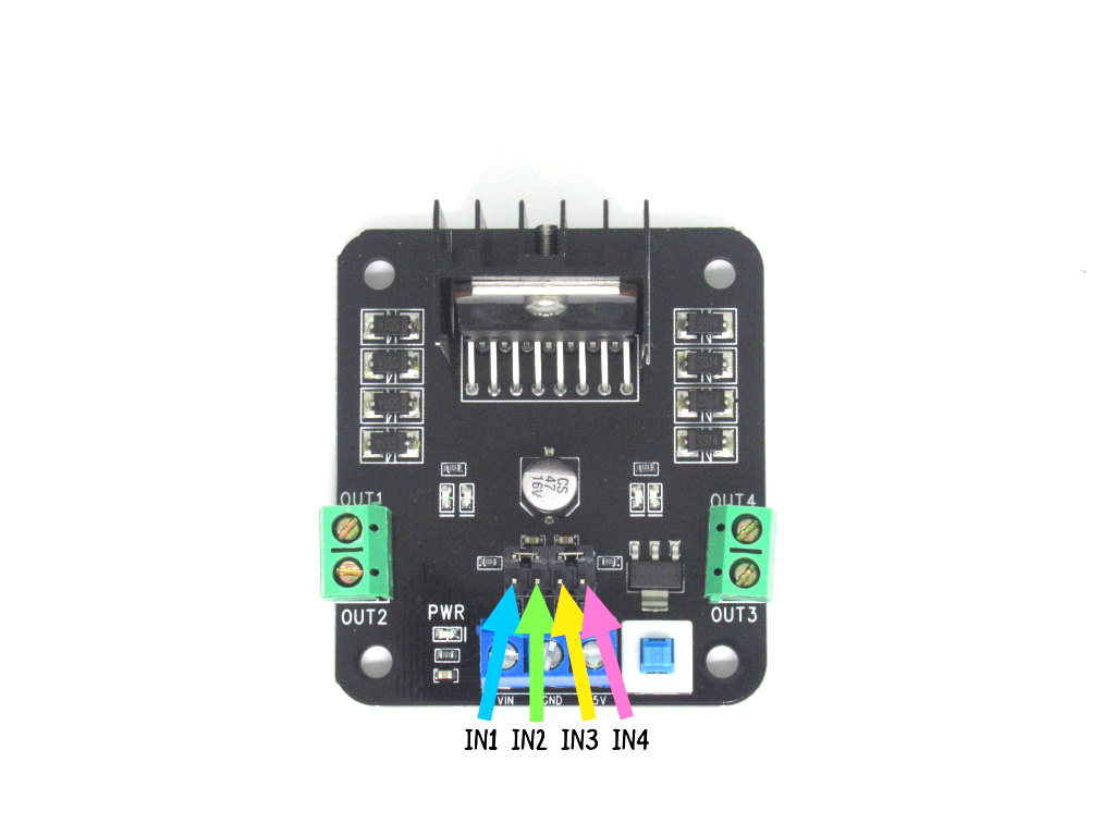
IN1 - The input to control Motor A
IN2 - The input to control Motor A
IN3 - The input to control Motor B
IN4 - The input to control Motor B
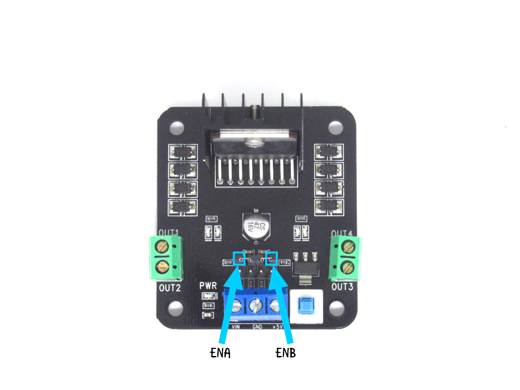
ENA enables motor A, whereas ENB enables motor B. Both of these need to be connected to PWM capable pins on the micro:bit. In this guide, we'll connect them to pins 2 and 3, respectively.
VIN - The VIN pin will be connected to the red wire of our 5V power supply
GND - This is the ground pin that we'll connect the black wire of our 5V power supply, and GND on the micro:bit.
5V - This is the 5V pin which we'll connect to 5V on the micro:bit
IN1 - The input to control Motor A
IN2 - The input to control Motor A
IN3 - The input to control Motor B
IN4 - The input to control Motor B
ENA enables motor A, whereas ENB enables motor B. Both of these need to be connected to PWM capable pins on the micro:bit. In this guide, we'll connect them to pins 2 and 3, respectively.
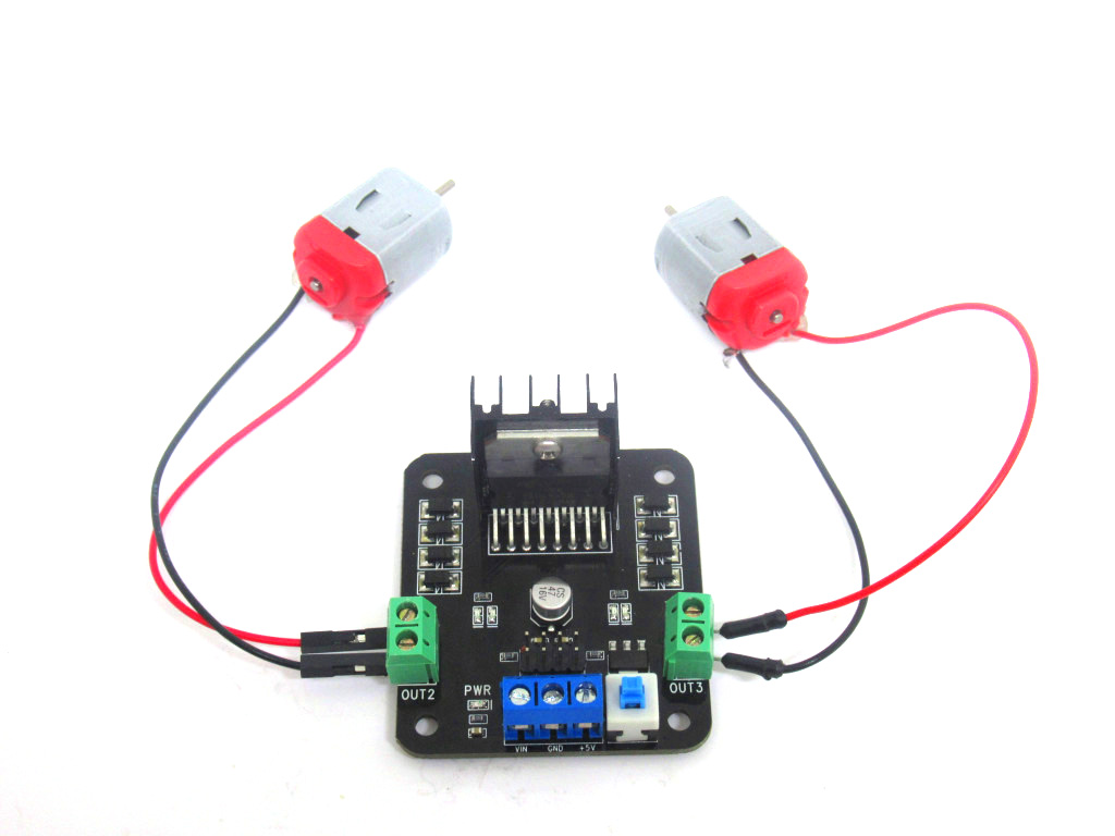
OUT1 and OUT2 will be connected to the first DC motor, Motor A's red and black wires.
OUT3 and OUT4 will be connected to the second DC motor, which we'll call Motor B.
OUT3 and OUT4 will be connected to the second DC motor, which we'll call Motor B.
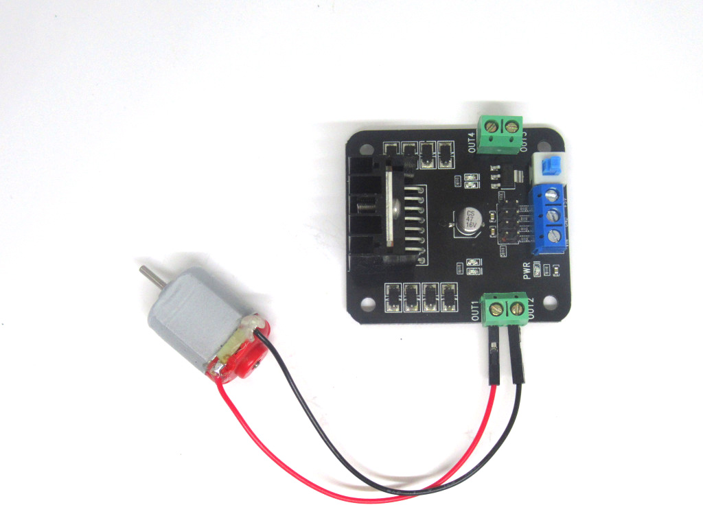
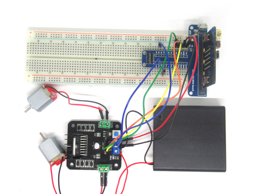
Connect the red wire of the DC motor to OUT1
Connect the black wire of the DC motor to OUT2
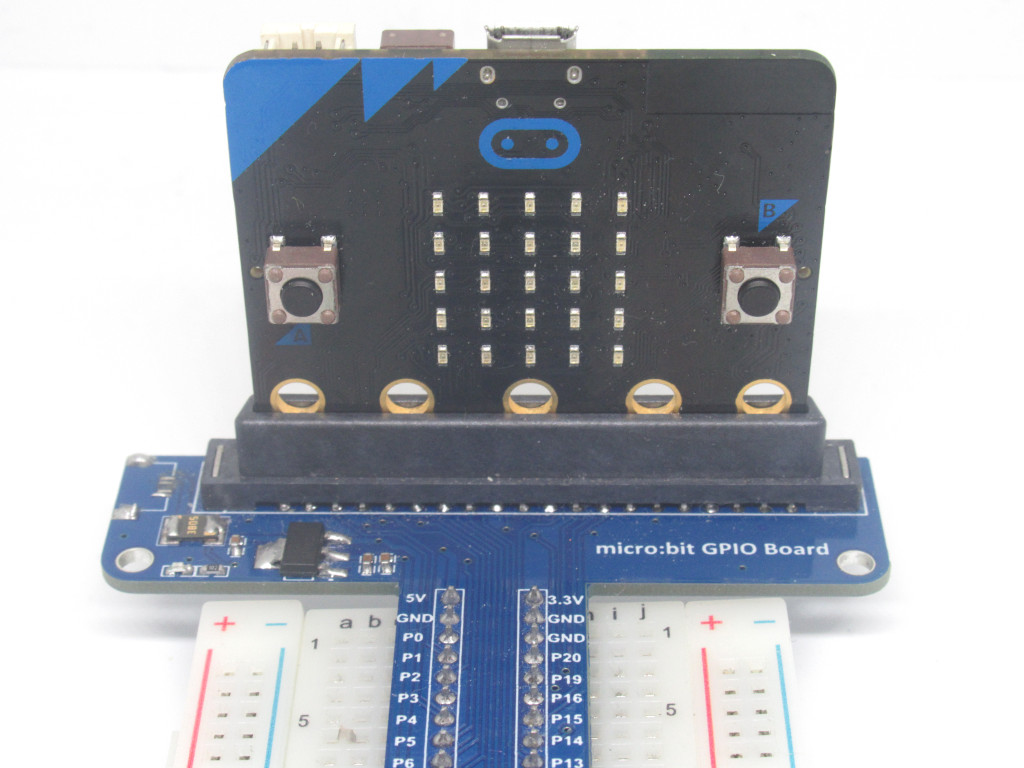
Insert the Micro:bit GPIO T-type Expansion Board into the breadboard, making sure that it is inserted from E1 to E13, and F1 to F13.
Insert the micro:bit into the breakout board.
Make sure that the micro:bit is inserted in the right orientation, with the buttons facing inward as shown.
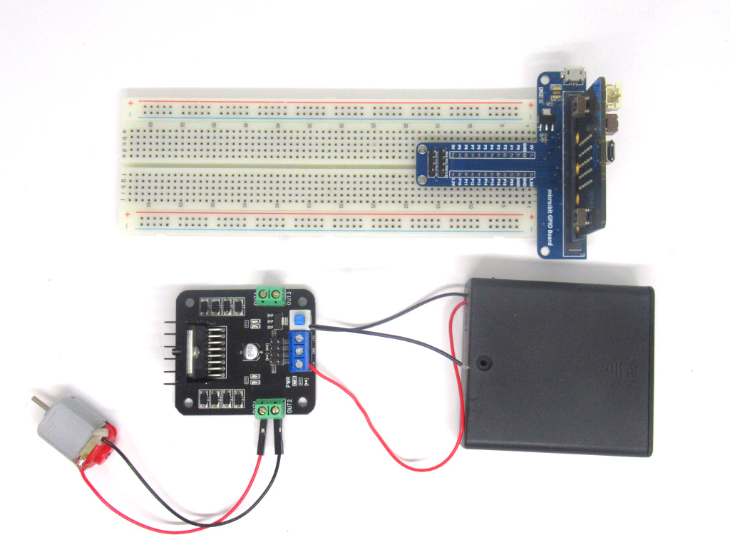
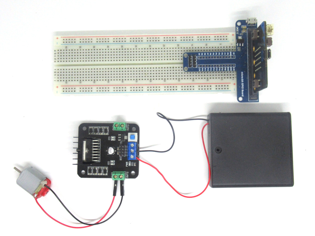
Connect the battery holder's red wire to VIN
Connect the battery holder's black wire to GND
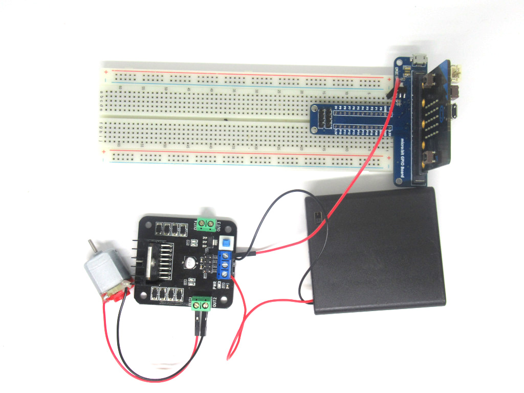
Connect a red jumper wire from +5V on the L298 H-Bridge Motor Driver to 5V on the micro:bit.
Connect a black jumper wire from GND on the L298 H-Bridge Motor Driver to GND on the micro:bit
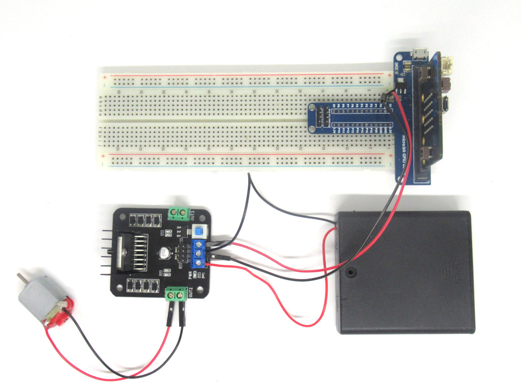
Attach a jumper wire into the breadboard from tiepoint A3 to IN1 on the L298 H-Bridge Motor Driver.
This will connect IN1 on the L298 H-Bridge Motor Driver to P0 on the micro:bit
Attach a jumper wire into the breadboard from tiepoint A4 to IN2 on the L298 H-Bridge Motor Driver.
This will connect IN2 on the L298 H-Bridge Motor Driver to P1 on the micro:bit
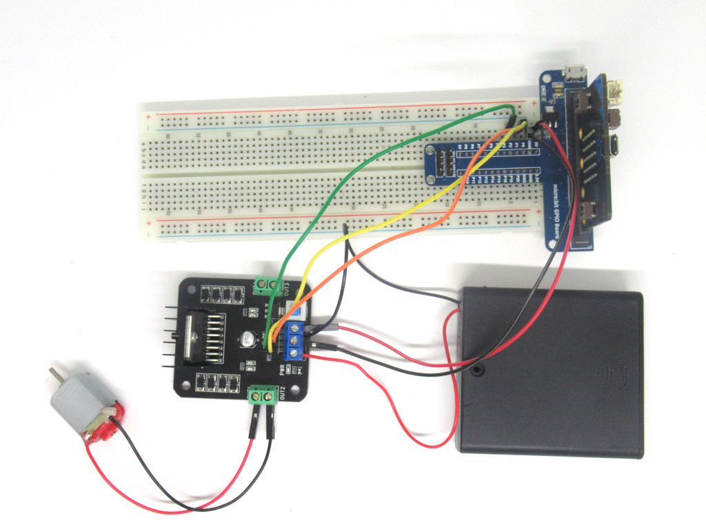
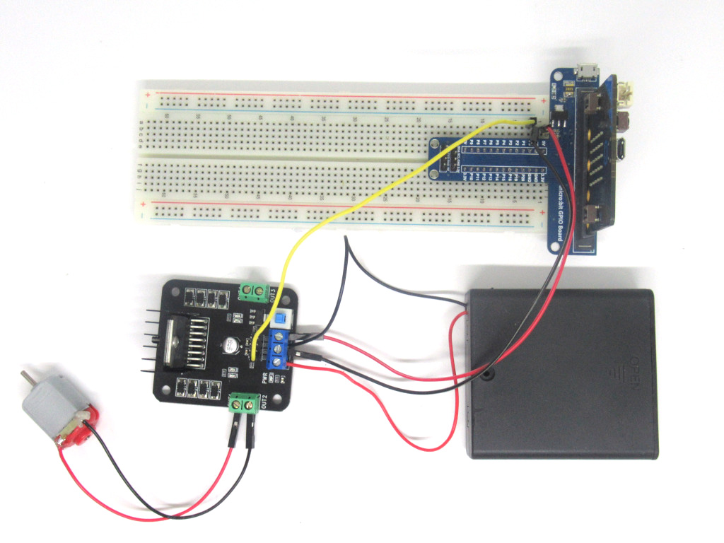
Attach a jumper wire into the breadboard from tiepoint A4 to ENA on the L298 H-Bridge Motor Driver.
This will connect ENA on the L298 H-Bridge Motor Driver to P2 on the micro:bit.
function motor () {
    pins.digitalWritePin(DigitalPin.P2, 1)
    pins.digitalWritePin(DigitalPin.P0, 1)
    pins.digitalWritePin(DigitalPin.P1, 0)
}
input.onButtonPressed(Button.A, function () {
    motor()
    basic.pause(100)
})
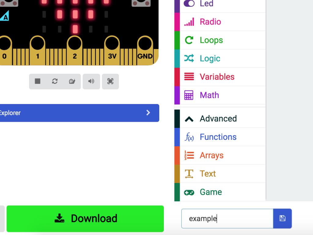
Open up the MakeCode editor
Click on 'New Project'
Click on the 'Javascript' button to access the Javascript interface
Copy and paste this code into the Javascript interface
Jump to the final step for instructions on how to upload the code to the micro:bit
Press Button A and the motor will rotate forwards.
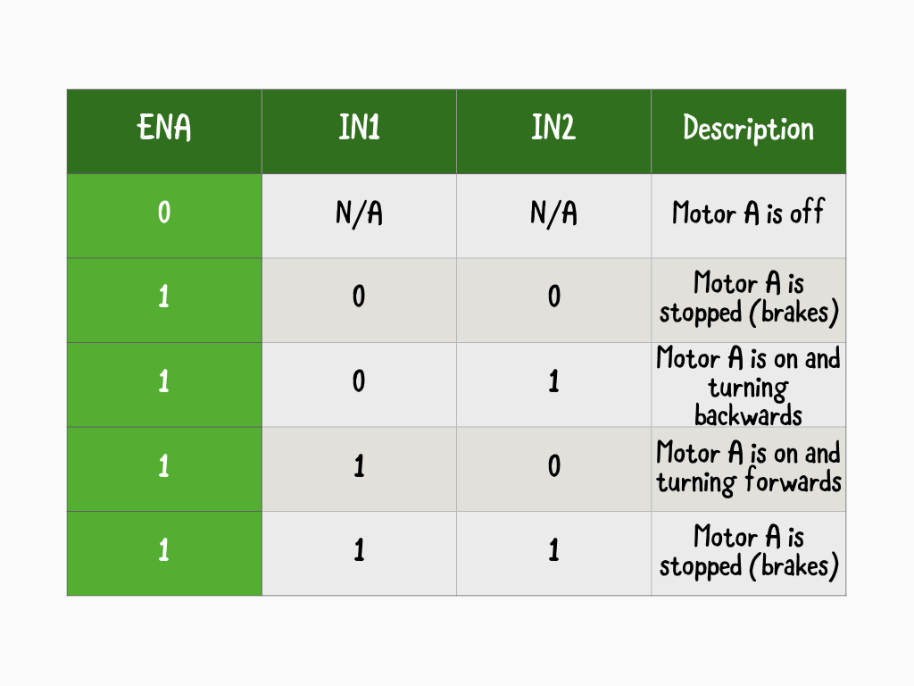

Here are two tables outlining the various modes of operation. Previously, Motor A rotated forwards as we've programmed it so that ENA pin is set to 'HIGH' or '1', IN1 is set to '1', and IN2 set to LOW or '0'.
Try changing the previous program so that Motor A is stopped, without needing to press the reset button.
function motor() {
    pins.digitalWritePin(DigitalPin.P2, 1)
    pins.digitalWritePin(DigitalPin.P0, 0)
    pins.digitalWritePin(DigitalPin.P1, 1)
}
input.onButtonPressed(Button.A, function () {
    motor()
    basic.pause(100)
})
Replace the previous code with the following.
By pressing Button A, the motor will now rotate backwards instead of forwards.
function motor () {
    pins.digitalWritePin(DigitalPin.P2, 1)
    pins.digitalWritePin(DigitalPin.P0, 1)
    pins.digitalWritePin(DigitalPin.P1, 0)
}
function halt () {
    pins.digitalWritePin(DigitalPin.P2, 0)
}
input.onButtonPressed(Button.B, function () {
    halt()
    basic.pause(100)
})
input.onButtonPressed(Button.A, function () {
    motor()
    basic.pause(100)
})
After testing the previous code, replace it with the following code in the Javascript interface
This time, after pressing Button A, you can press Button B to stop the motor from rotating.
Connect the black wire from the DC motor to OUT3 on the L298 H-Bridge Motor Driver.
Connect the red wire from the DC motor to OUT4 on the L298 H-Bridge Motor Driver.
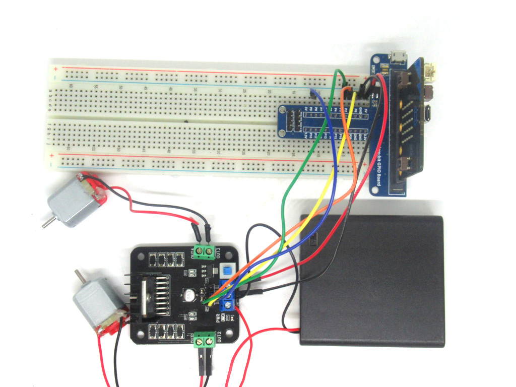
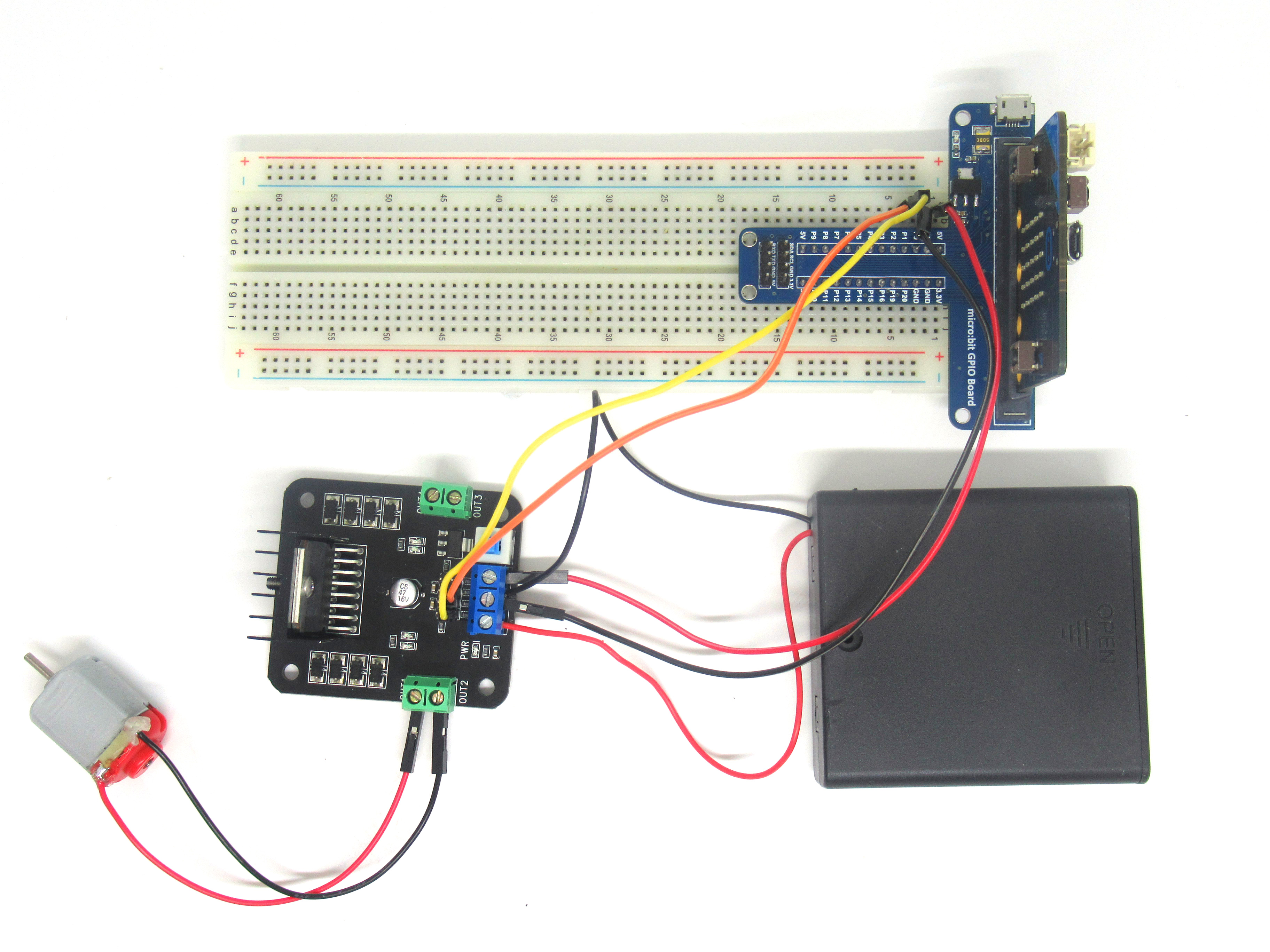
Connect a jumper wire from tiepoint A11 to IN3 on the L298 H-Bridge Motor Driver.
Connect a jumper wire from tiepoint J10 to IN4 on the L298 H-Bridge Motor Driver.
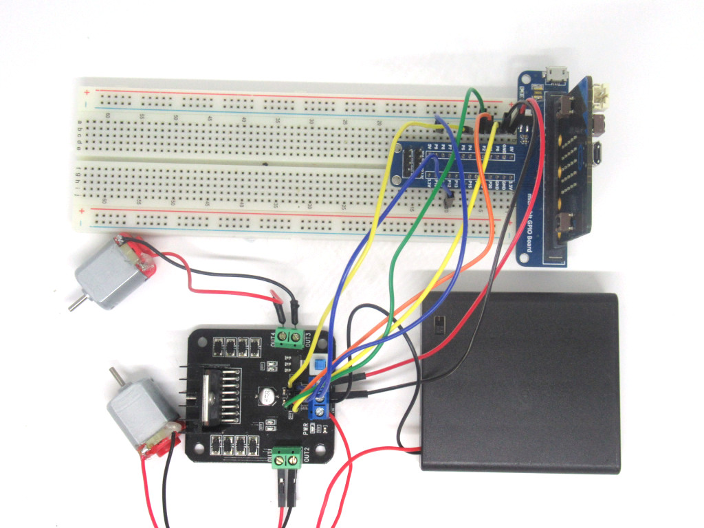
Attach a jumper wire into the breadboard from tiepoint A6 to ENB on the L298 H-Bridge Motor Driver
function motor () {
    pins.digitalWritePin(DigitalPin.P2, 1)
    pins.digitalWritePin(DigitalPin.P0, 1)
    pins.digitalWritePin(DigitalPin.P1, 0)
    pins.digitalWritePin(DigitalPin.P3, 1)
    pins.digitalWritePin(DigitalPin.P8, 1)
    pins.digitalWritePin(DigitalPin.P12, 0)
}
input.onButtonPressed(Button.A, function () {
    motor()
})
basic.forever(function () {
    led.enable(false)
})
Replace the existing code with the following in the Javascript interface.
By pressing Button A, both motors will now rotate forwards.
function motor() {
    pins.digitalWritePin(DigitalPin.P2, 1)
    pins.digitalWritePin(DigitalPin.P0, 0)
    pins.digitalWritePin(DigitalPin.P1, 1)
    pins.digitalWritePin(DigitalPin.P3, 1)
    pins.digitalWritePin(DigitalPin.P8, 0)
    pins.digitalWritePin(DigitalPin.P12, 1)
}
input.onButtonPressed(Button.A, function () {
    motor()
})
basic.forever(function () {
    led.enable(false)
})
Press Button A after uploading this code to the micro:bit. Both motors should now rotate backwards!
function forwards() {
    pins.digitalWritePin(DigitalPin.P2, 1)
    pins.digitalWritePin(DigitalPin.P0, 1)
    pins.digitalWritePin(DigitalPin.P1, 0)
    pins.digitalWritePin(DigitalPin.P3, 1)
    pins.digitalWritePin(DigitalPin.P8, 1)
    pins.digitalWritePin(DigitalPin.P12, 0)
}

function backwards() {
    pins.digitalWritePin(DigitalPin.P2, 1)
    pins.digitalWritePin(DigitalPin.P0, 0)
    pins.digitalWritePin(DigitalPin.P1, 1)
    pins.digitalWritePin(DigitalPin.P3, 1)
    pins.digitalWritePin(DigitalPin.P8, 0)
    pins.digitalWritePin(DigitalPin.P12, 1)
}

input.onButtonPressed(Button.A, function () {
    forwards()
})

input.onButtonPressed(Button.B, function () {
    backwards()
})

basic.forever(function () {
    led.enable(false)
})
Replace the previous code with this updated code.
We have created two new functions, 'forwards' and 'backwards'. When Button A is pressed, it calls the forwards() function and both motors will rotate forwards. If Button B is pressed, it calls the backwards() function and both motors will rotate backwards
Press the reset button and both motors will stop rotating.
Connect a microUSB cable to the micro USB port of the micro:bit
Then connect the other end of the cable to your computer or laptop's USB port
Click on the Download button on the bottom left-hand corner of the Makecode screen
Find the hex file in the Downloads folder or other folder that you might have moved it to
Open up Finder on the MacOS or Explorer on Windows, and drag the hex file into MICROBIT under 'Devices' on the macOS.
Watch the micro:bit flash for a few seconds. Let the LED continue to flash until it is done, then unplug it.