Building the Pong Game Hardware
Written By: Cherie Tan
Difficulty
Medium
Steps
16
Pong is one of the earliest arcade games, released in 1972.
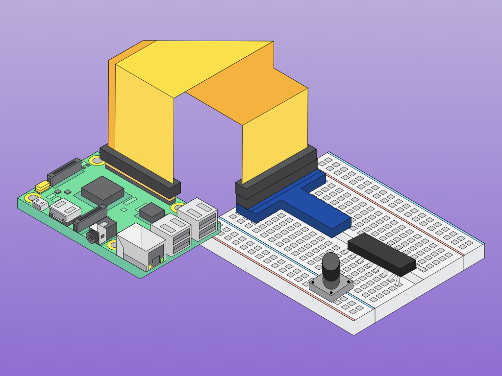
In this guide, you will build a hardware controller using a Raspberry Pi to play the old-school classic, Pong.
Complete this guide to get started and make customisations to your build.
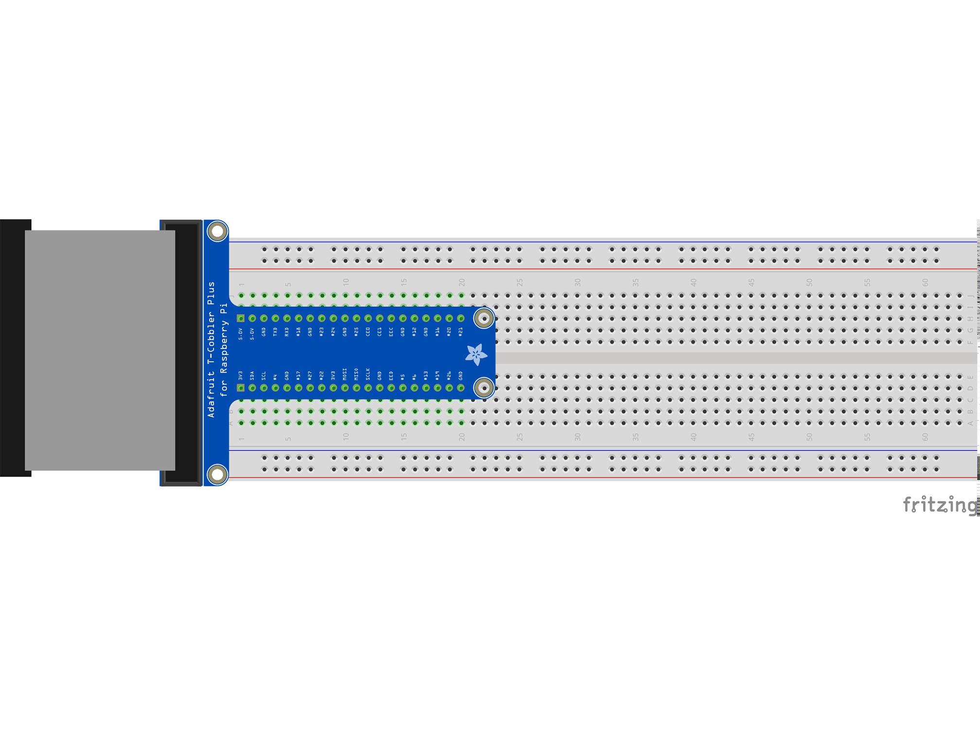
This is the Pi T-Cobbler. It breaks out the GPIO pins from the Pi allowing us to connect cool stuff
Firmly press the cobbler into the breadboard making sure the first 5.0v pin is in H1
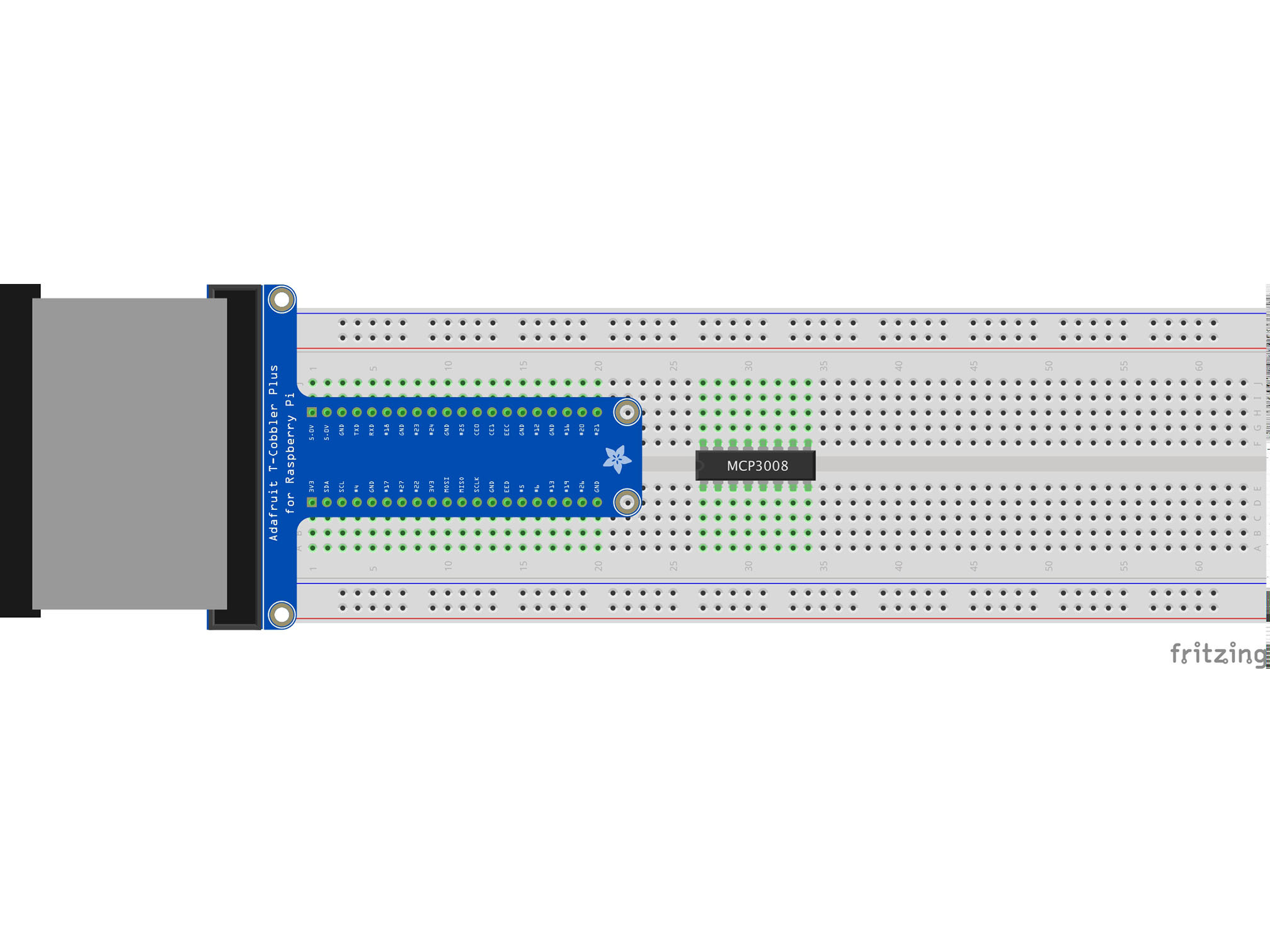

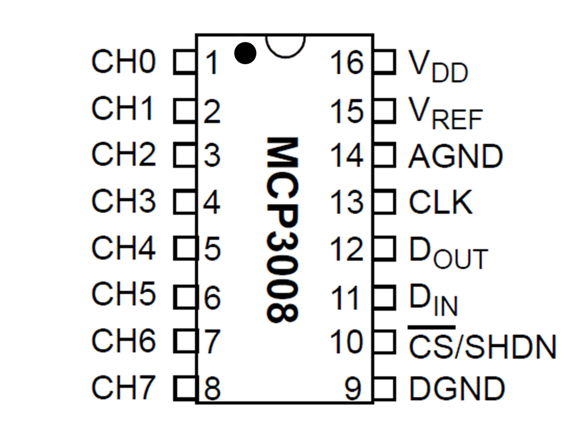
This IC (integrated circuit) is an analog to digital converter allowing us to read analog inputs into our Pi
Line up pin 1 (marked by a small indent on the plastic) with E27
Press firmly into the breadboard
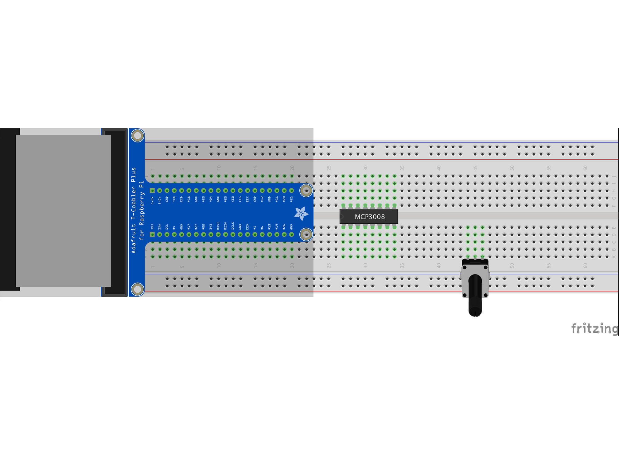
This is a potentiometer. It will be our analog input.
Press it into the breadboard as shown with the first pin in A44

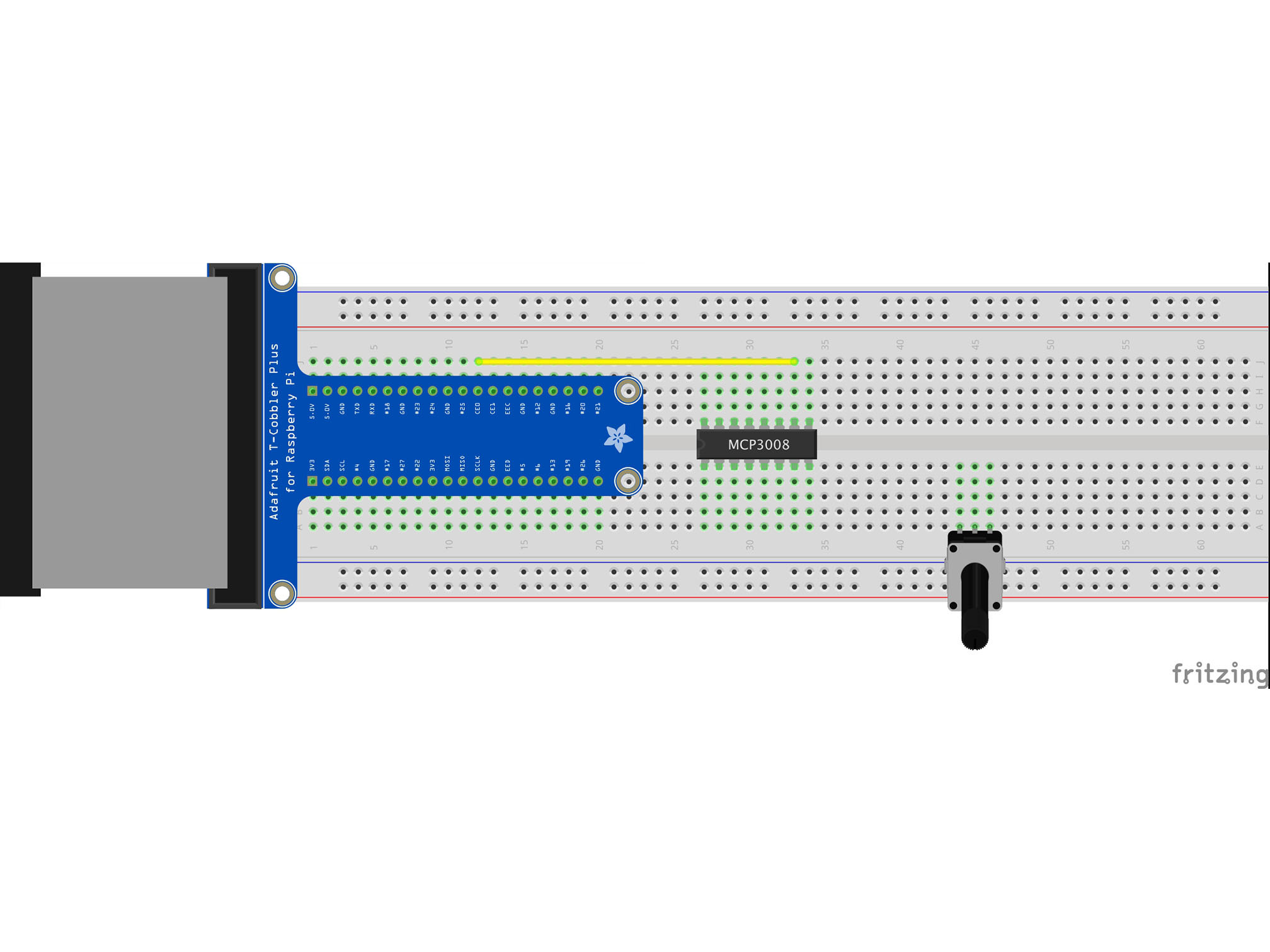
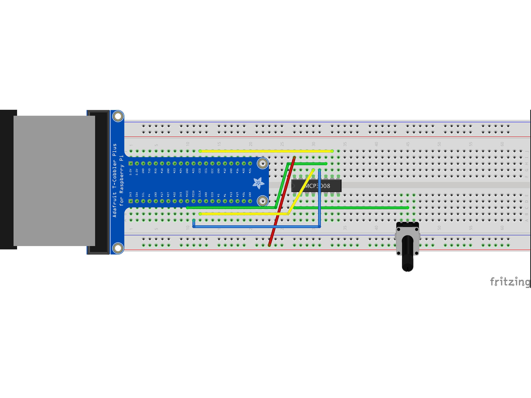
Connect J12 to J33 using a yellow jumper wire
This is our chip select line
It tells the IC when it can send data
MCP3008 CS/SHDN to Raspberry Pi CE0


Connect J30 to B12 using a yellow jumper wire
This is our data clock, it allows the Pi to synchronize data transfer with the IC
MCP3008 CLK to Raspberry Pi SCLK


Connect C10 to H30 using a green jumper wire
This is our MOSI (Master Output Slave Input)
It allows the Pi to talk to the IC
MCP3008 DIN to Raspberry Pi MOSI


Connect G31 to A11 using a blue jumper wire
This is out MISO (Master Input Slave Output)
It allows our IC to talk to the Pi
MCP3008 DOUT to Raspberry Pi MISO
Connect the RED power rail to I27 with a red jumper cable
This is providing power connection to our IC
MCP3008 VDD to Raspberry Pi 3.3V
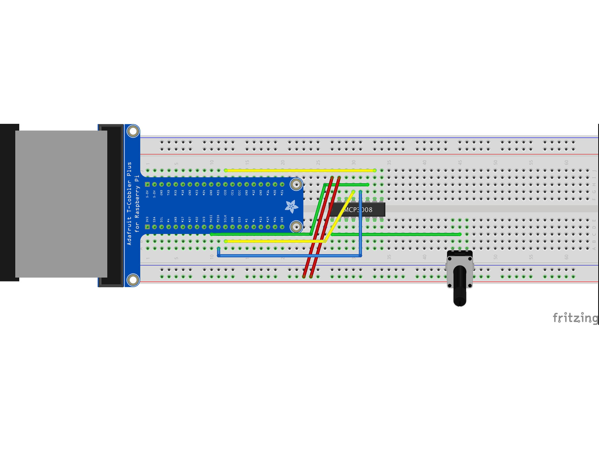

Connect the RED power rail to I28 using a red jumper cable
This is our Vref
It provides a reference voltage to measure our analog input against MCP3008 VREF to Raspberry Pi 3.3V

Connect the BLUE power rail to G29 using a black jumper cable
This is our analog signal negative (ground or GND) connection to the IC
MCP3008 AGND to Raspberry Pi GND
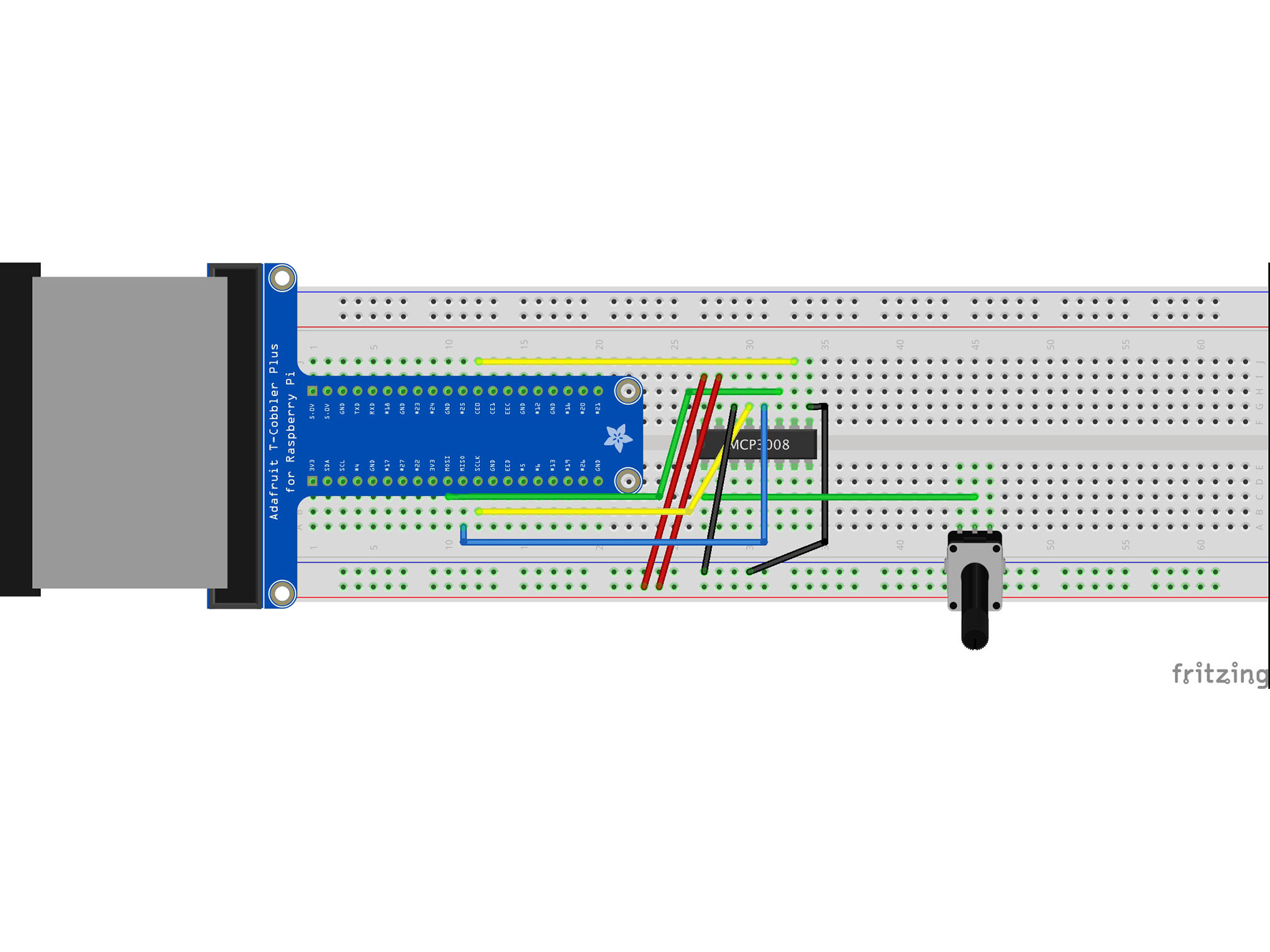
Connect G34 to the BLUE power rail with a black jumper cable
This is our negative (ground or GND) connection to the IC
MCP3008 DGND to Raspberry Pi GND

Connect the BLUE power rail to B46 with a black jumper cable
This is our negative (GND) connection the the potentiometer

Connect the RED power rail to B44 with a red jumper cable
This is our positive connection the the Potentiometer
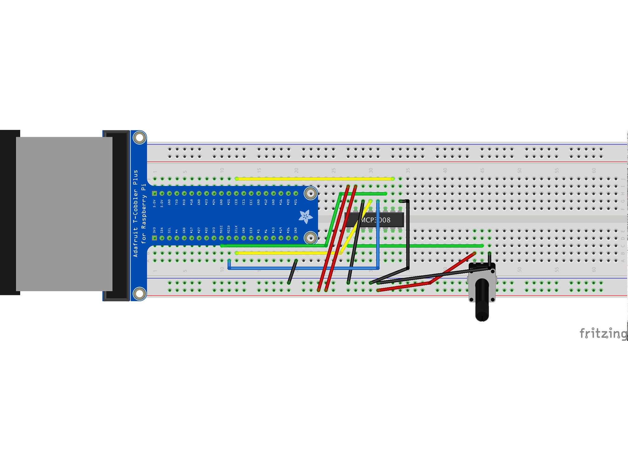
Connect the BLUE power rail to A20 with a black jumper cable
This allows the raspberry Pi to share a ground (negative, GND) connection with the rest of our circuit
