3D Printed Heart Rate Indicator
Make a simple and colourful heart rate indicator with the EagLED
Written By: Cherie Tan

Difficulty
Medium
Steps
18
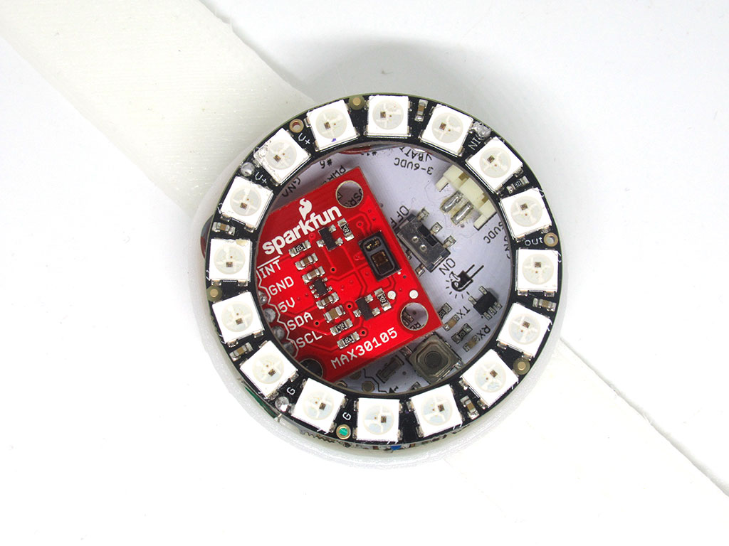
The MAX30105 breakout board is a versatile sensor capable of sensing distance, heart rate, particles, and even the blinking of an eye.
In this guide, we will begin with obtaining heart rate measurements from the MAX30105, then use these measurements with an RGB LED ring and an EagLED.
Complete this guide to create a simple heart rate monitor indicated by colours, with the EagLED!
In this guide, we will begin with obtaining heart rate measurements from the MAX30105, then use these measurements with an RGB LED ring and an EagLED.
Complete this guide to create a simple heart rate monitor indicated by colours, with the EagLED!
Previously, we showed you how to create a breath pacer device as well as a pulse monitor with the EagLED and Pulse Sensor Amped which uses photoplethysmography, a non-invasive method for heart-rate monitoring.
In this guide, learn to use the MAX30105 Pulse Oximetry sensor with a Neopixel RGB LED ring (16 pixels) to create a simple heart rate monitor, indicated by colours.
In this guide, learn to use the MAX30105 Pulse Oximetry sensor with a Neopixel RGB LED ring (16 pixels) to create a simple heart rate monitor, indicated by colours.
The MAX30105 breakout board is a versatile sensor capable of sensing distance, heart rate, particles, and even the blinking of an eye. For more information, check out the MAX30105 datasheet.
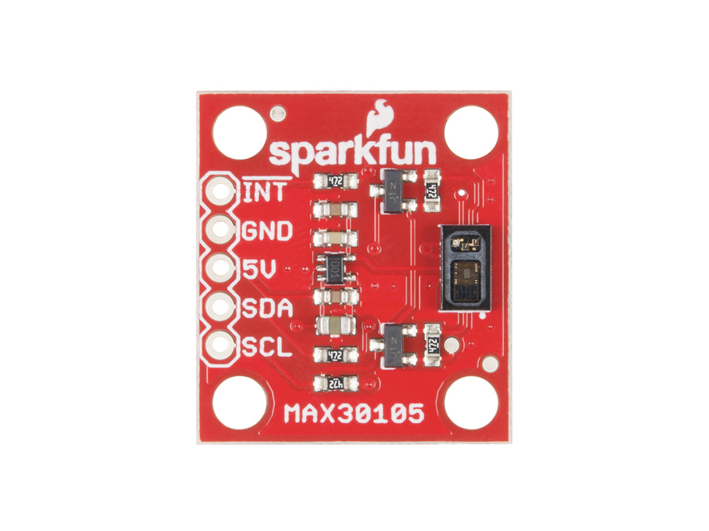
It has 5 pins:
INT : Interrupt pin
GND : Ground
5V : Power supply
SDA : Bi-directional data line.
SCL : Clock line
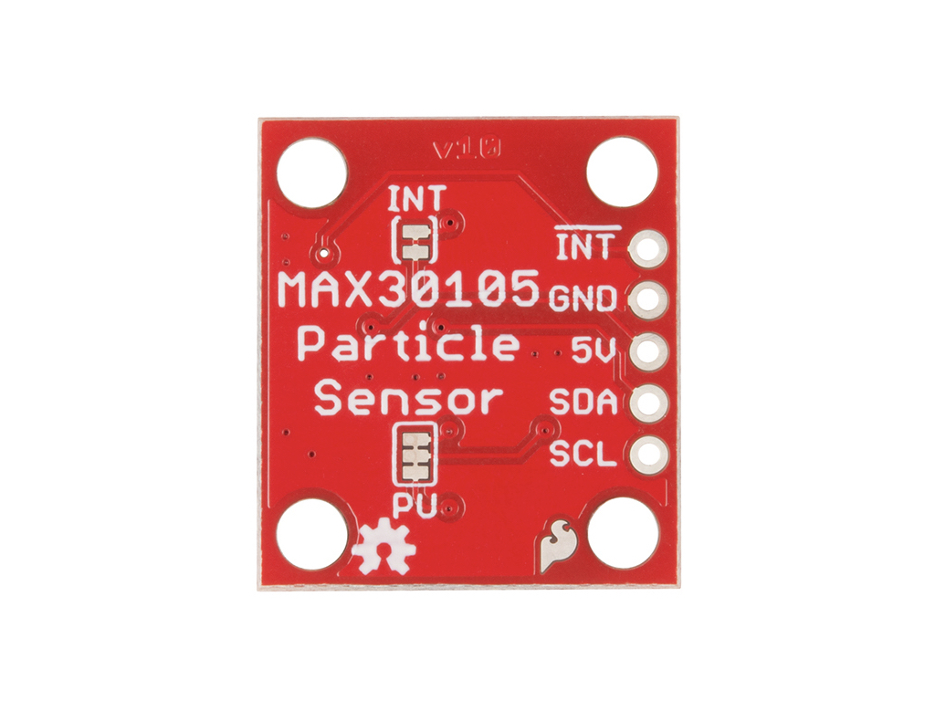
An additional two pins on the back:
INT : This is used to control the pull-up resistor on the interrupt pin. It is closed by default, which means a 4.7k resistor is pulling up the interrupt pin. If only one board is used on the I2C bus, this should be left alone. Otherwise, if there are multiple boards in use on the I2C bus sharing a single interrupt pin, this jumper can be cut to disconnect the pull-up resistor.
PU : This jumper is used on many I2C boards to allow the user to disconnect the 4.7k ohm pull-up resistors from SDA and SCL lines. By default, it is also closed, which means the 4.7k resistor is pulling up the SDA and SCL pins. If there is only one device on the I2C bus, leave this untouched. If there are multiple devices on the bus with pull-up resistors, then the traces on this jumper can be cut to remove the 4.k ohm resistors from the bus.
INT : Interrupt pin
GND : Ground
5V : Power supply
SDA : Bi-directional data line.
SCL : Clock line
An additional two pins on the back:
INT : This is used to control the pull-up resistor on the interrupt pin. It is closed by default, which means a 4.7k resistor is pulling up the interrupt pin. If only one board is used on the I2C bus, this should be left alone. Otherwise, if there are multiple boards in use on the I2C bus sharing a single interrupt pin, this jumper can be cut to disconnect the pull-up resistor.
PU : This jumper is used on many I2C boards to allow the user to disconnect the 4.7k ohm pull-up resistors from SDA and SCL lines. By default, it is also closed, which means the 4.7k resistor is pulling up the SDA and SCL pins. If there is only one device on the I2C bus, leave this untouched. If there are multiple devices on the bus with pull-up resistors, then the traces on this jumper can be cut to remove the 4.k ohm resistors from the bus.
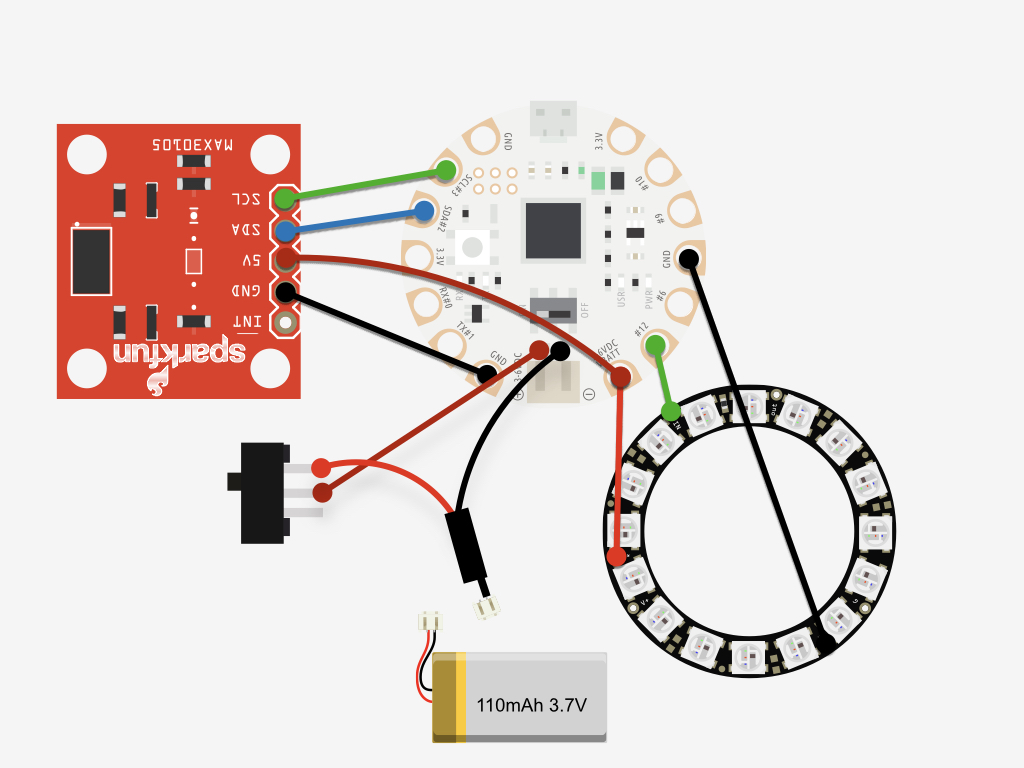
The complete circuit diagram is as shown. In the following steps, we'll break it down and show you how to make each connection one step at a time.


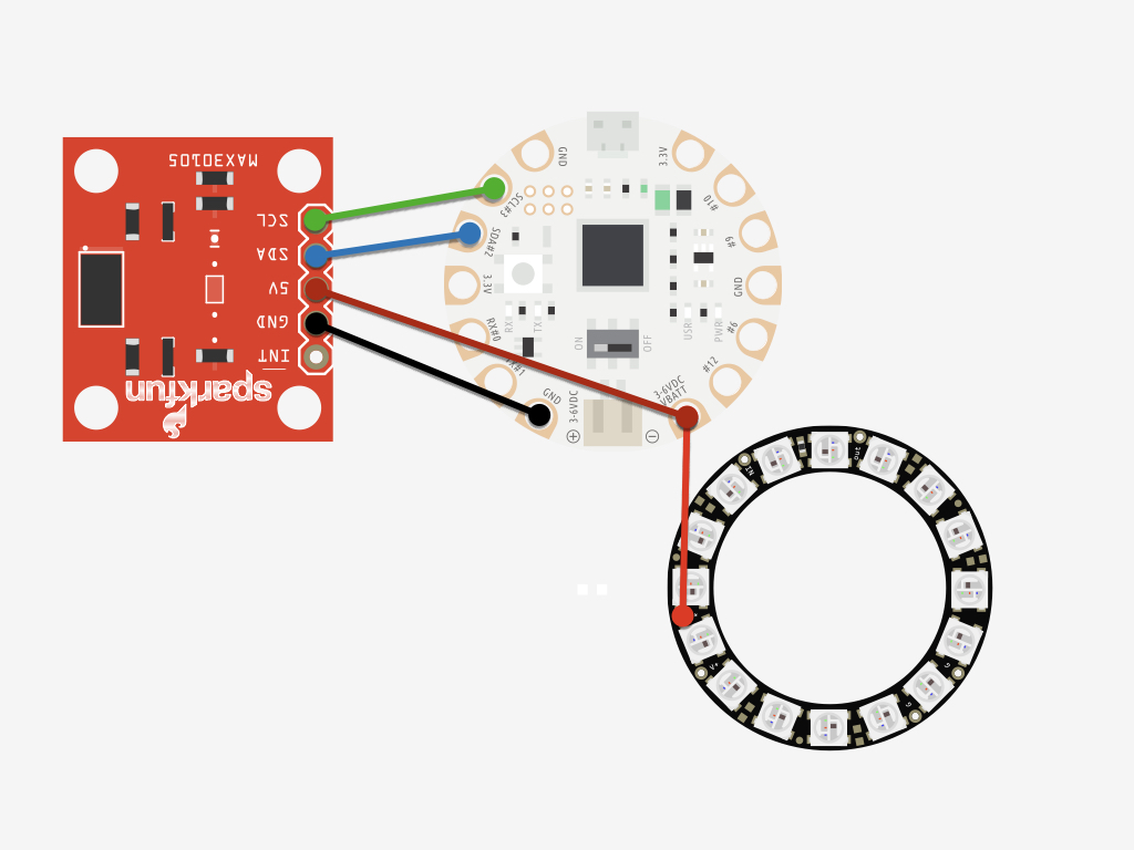
Solder a jumper wire from 5V on the Neopixel RGB LED ring to SCL#3 on the EagLED.
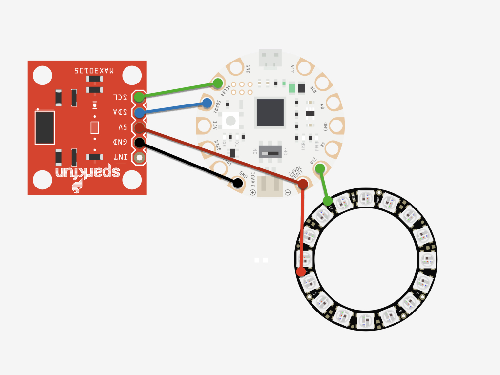
Solder a jumper wire from IN on the Neopixel RGB LED ring to #12 on the EagLED.
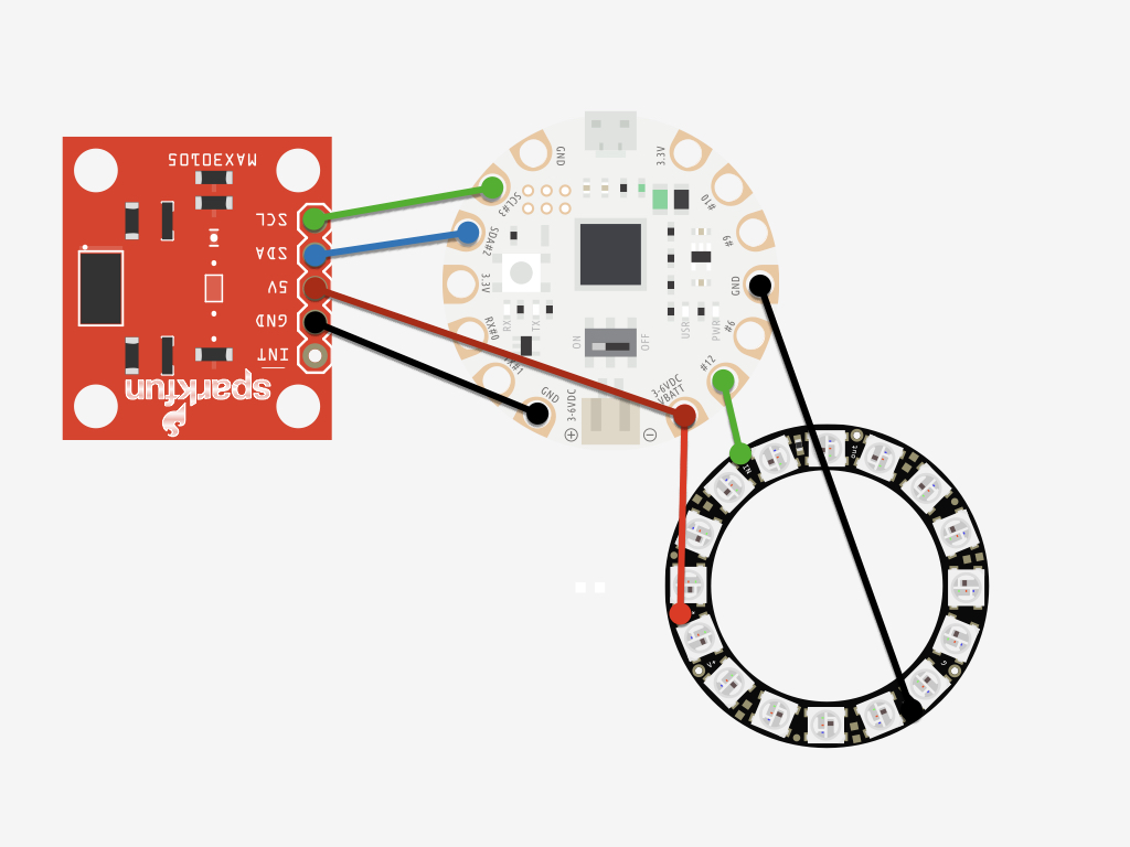
Solder a jumper wire from GND on the Neopixel RGB LED ring to GND on the EagLED.
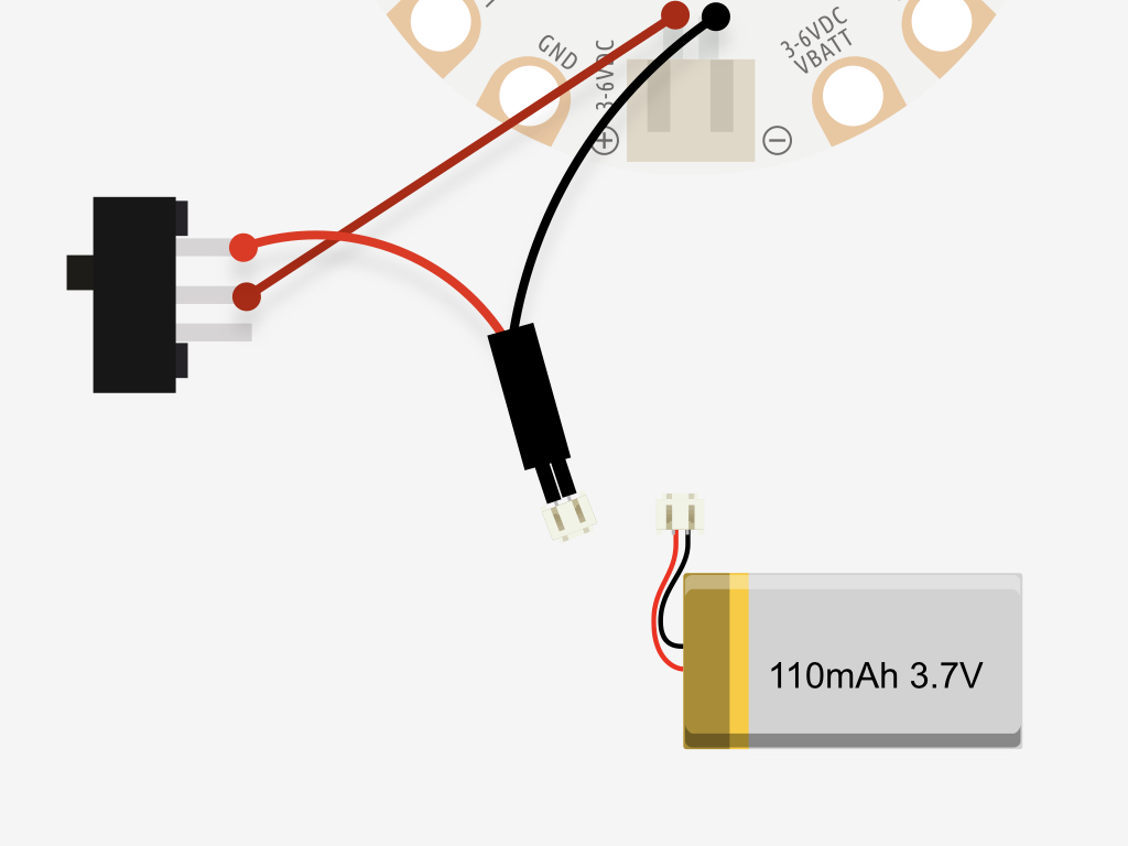
Next, to make the circuit as compact as it can be, it's time to add a JST extension cable to an SPST switch and a LiPo battery. First, cut the JST extension cable in half, then solder the red cable to the outer leg of the slide switch.
Solder the black cable to '-' on the JST Connector of the EagLED.
Then, solder a red wire from the SPST slid switch to '+' on the JST Connector of the EagLED.
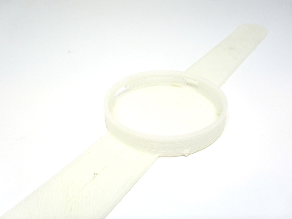
In this guide, we've used this flexible wrist strap from Thingiverse, printed in Ninjaflex, to place the components in.
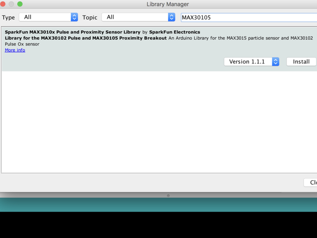
To start programming the MA30105, navigate to Tools > Manage Libraries ...
Type 'MAX30105' into the search field.
Click the Install button
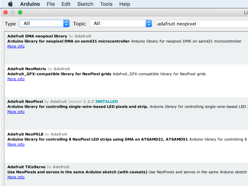
You will also need a library for the RGB LED Ring: Type 'adafruit neopixel' in the search field
Find 'Adafruit Neopixel'
Click on the 'Install' button
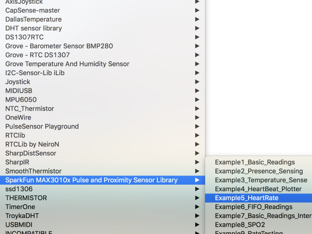
Upload this sketch to the EagLED.
Navigate to Files > Examples > SparkFun MAX3010x Pulse and Proximity Sensor Library > Example5_HeartRate

#include <Wire.h>
#include <Adafruit_NeoPixel.h>
#include "MAX30105.h"
#include "heartRate.h"

//  Variables
#define LED_PIN        6     // Pin on EagLED that RGB LED Ring is connected to
#define NUMPIXELS 16 // LEDs attached to EagLED

const byte RATE_SIZE = 4; //Increase this for more averaging. 4 is good.
byte rates[RATE_SIZE]; //Array of heart rates
byte rateSpot = 0;
long lastBeat = 0; //Time at which the last beat occurred
float beatsPerMinute;
int beatAvg;

Adafruit_NeoPixel pixels = Adafruit_NeoPixel(NUMPIXELS, LED_PIN, NEO_GRB + NEO_KHZ800);
MAX30105 particleSensor;

void setup() {
  Serial.begin(115200);
  pixels.begin(); // INITIALIZE NeoPixel strip object (REQUIRED)
  pixels.setBrightness(5);
  Serial.println("Initializing...");

  // Initialize sensor
  if (!particleSensor.begin(Wire, I2C_SPEED_FAST)) //Use default I2C port, 400kHz speed
  {
    Serial.println("MAX30105 was not found. Please check wiring/power. ");
    while (1);
  }
  Serial.println("Place your index finger on the sensor with steady pressure.");

  particleSensor.setup(); //Configure sensor with default settings
  particleSensor.setPulseAmplitudeRed(0x0A); //Turn Red LED to low to indicate sensor is running
  particleSensor.setPulseAmplitudeGreen(0); //Turn off Green LED
}
Replace the example sketch with the following.
#include <Wire.h>
#include <Adafruit_NeoPixel.h>
#include "MAX30105.h"
#include "heartRate.h"

//  Variables
#define LED_PIN        6     // Pin on EagLED that RGB LED Ring is connected to
#define NUMPIXELS 16 // LEDs attached to EagLED

const byte RATE_SIZE = 4; //Increase this for more averaging. 4 is good.
byte rates[RATE_SIZE]; //Array of heart rates
byte rateSpot = 0;
long lastBeat = 0; //Time at which the last beat occurred
float beatsPerMinute;
int beatAvg;

Adafruit_NeoPixel pixels = Adafruit_NeoPixel(NUMPIXELS, LED_PIN, NEO_GRB + NEO_KHZ800);
MAX30105 particleSensor;

void setup() {
  Serial.begin(115200);
  pixels.begin(); // INITIALIZE NeoPixel object (REQUIRED)
  pixels.setBrightness(5);
  Serial.println("Initializing...");

  // Initialize sensor
  if (!particleSensor.begin(Wire, I2C_SPEED_FAST)) //Use default I2C port, 400kHz speed
  {
    Serial.println("MAX30105 was not found. Please check wiring/power. ");
    while (1);
  }
  Serial.println("Place your index finger on the sensor with steady pressure.");

  particleSensor.setup(); //Configure sensor with default settings
  particleSensor.setPulseAmplitudeRed(0x0A); //Turn Red LED to low to indicate sensor is running
  particleSensor.setPulseAmplitudeGreen(0); //Turn off Green LED
}


void loop() {
  pixels.clear(); // Set all pixel colors to 'off'
  long irValue = particleSensor.getIR();

  if (checkForBeat(irValue) == true)
  {
    //We sensed a beat!
    long delta = millis() - lastBeat;
    lastBeat = millis();

    beatsPerMinute = 60 / (delta / 1000.0);

    if (beatsPerMinute < 255 && beatsPerMinute > 20)
    {
      rates[rateSpot++] = (byte)beatsPerMinute; //Store this reading in the array
      rateSpot %= RATE_SIZE; //Wrap variable

      //Take average of readings
      beatAvg = 0;
      for (byte x = 0 ; x < RATE_SIZE ; x++)
        beatAvg += rates[x];
      beatAvg /= RATE_SIZE;
    }
  }

  for (int i = 0; i < NUMPIXELS; i++) {
    if (irValue < 50000) {
      pixels.setPixelColor(i, pixels.Color(255, 255, 255));
      pixels.show();
    }
    else if (irValue > 50000) {
      if (beatAvg <= 60) {
        pixels.setPixelColor(i, pixels.Color(0, 150, 0));
        pixels.show();   // Send the updated pixel colors to the hardware.
      }
      else if (beatAvg > 100) {
        pixels.setPixelColor(i, pixels.Color(255, 0, 0));
        pixels.show();   // Send the updated pixel colors to the hardware.
      }
      else if (beatAvg < 100 && beatAvg > 60) {
        pixels.setPixelColor(i, pixels.Color(0, 0, 255));
        pixels.show();   // Send the updated pixel colors to the hardware.
      }
    }
  }
}
Next, add the following code to the sketch.
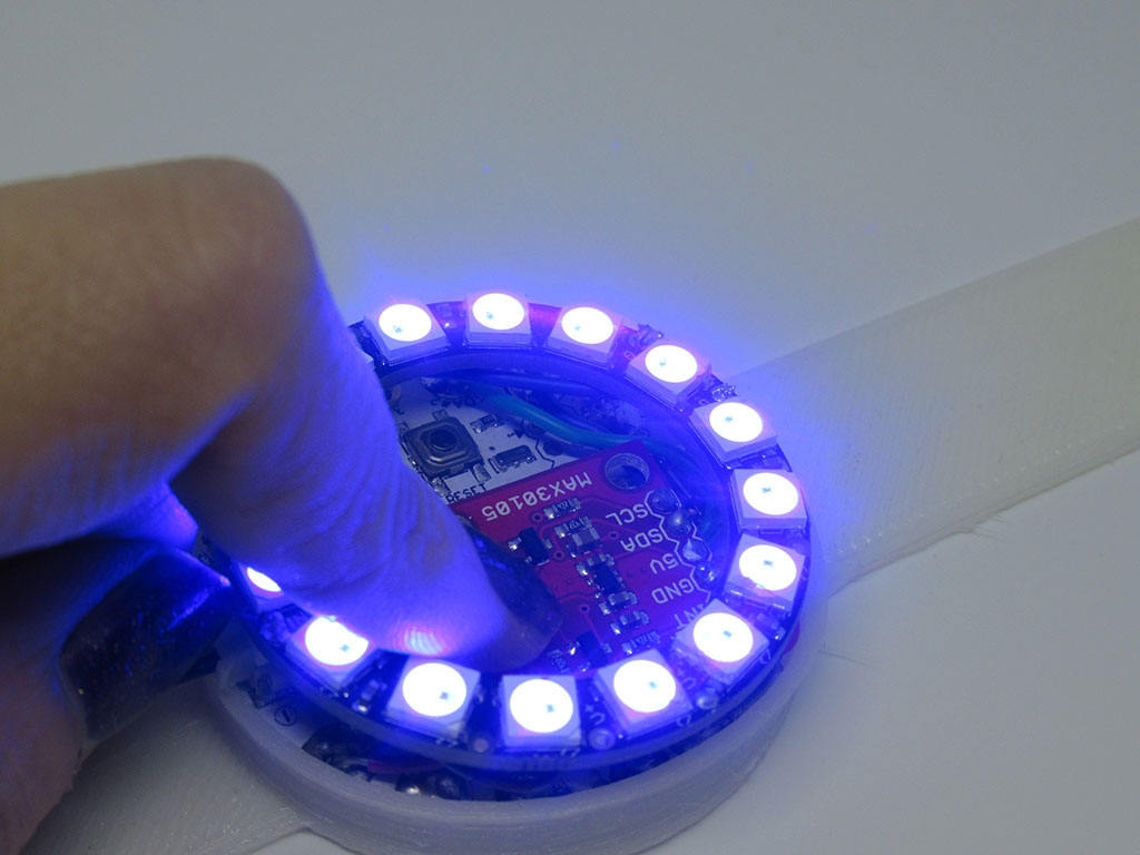
If the irValue is less than 50000 then that would mean there is no finger detected, and the LEDs will light up in white.
If the irValue is larger than 50000, then a finger is detected, and if the beatAvg is less than or equal to 60, the LEDs will light up in green.
If the beatAvg is larger than 100, then the LEDs will light up in red.
Otherwise, it will light up in blue.
If the irValue is larger than 50000, then a finger is detected, and if the beatAvg is less than or equal to 60, the LEDs will light up in green.
If the beatAvg is larger than 100, then the LEDs will light up in red.
Otherwise, it will light up in blue.
Please note that as we are detecting heart-rate optically, it is tricky and prone to give false readings at times. Use this code only as an example of how to process optimal data. Not suitable for actual medical diagnosis!
Alternatively, as the MAX30105 has a range of other sensing capabilities, you could get the RGB LED ring to light up in different colours according to the temperature, or simply from particle detection.